RUT955 VLAN (legacy WebUI)
The information in this page is updated in accordance with firmware version RUT9XX_R_00.06.09.5.
Note: this user manual page is for RUT955's old WebUI style available in earlier FW versions. Click here for information based on the latest FW version.
Summary
A virtual LAN (VLAN) is any broadcast domain that is partitioned and isolated in a computer network at the data link layer (OSI layer 2). LAN is the abbreviation for local area network and in this context virtual refers to a physical object recreated and altered by additional logic. VLANs work by applying tags to network packets and handling these tags in networking systems - creating the appearance and functionality of network traffic that is physically on a single network but acts as if it is split between separate networks. In this way, VLANs can keep network applications separate despite being connected to the same physical network, and without requiring multiple sets of cabling and networking devices to be deployed.
VLANs allow network administrators to group hosts together even if the hosts are not on the same network switch. This can greatly simplify network design and deployment, because VLAN membership can be configured through software. Without VLANs, grouping hosts according to their resource needs necessitates the labor of relocating nodes or rewiring data links. It also has benefits in allowing networks and devices that must be kept separate to share the same physical cabling without interacting, for reasons of simplicity, security, traffic management, or economy. For example, a VLAN could be used to separate traffic within a business due to users, and due to network administrators, or between types of traffic, so that users or low priority traffic cannot directly affect the rest of the network's functioning. Many Internet hosting services use VLANs to separate their customers' private zones from each other, allowing each customer's servers to be grouped together in a single network segment while being located anywhere in their datacenter. Some precautions are needed to prevent traffic "escaping" from a given VLAN, an exploit known as VLAN hopping.
This chapter is an overview of the VLAN function of RUT devices.
VLAN Networks
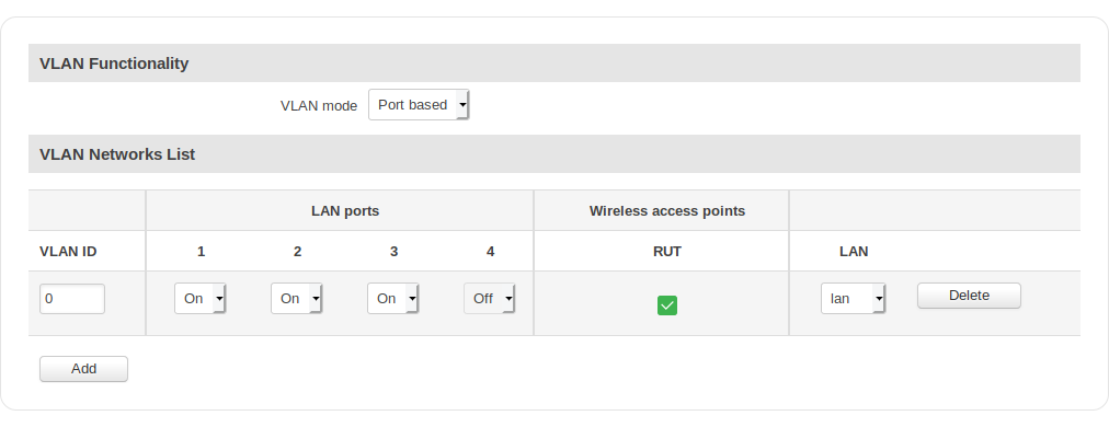
The VLAN Networks tab is used to enable Port based or Tag based VLAN.
As you can see in the image above, VLAN is disabled by default. To enable VLAN functionality, select either Port based or Tag based VLAN mode.
VLAN Functionality
Once you have selected the desired functionality, you will be able to configure it.
Port Based
Port based VLAN is a method to create separate LAN networks on different LAN ports. The method is pretty simple: first you have to configure an alternate LAN network, then you have to choose which LAN port (s) will provide addresses for that network. More detailed information is provided in the table below.
| field name | value | description |
|---|---|---|
| VLAN ID | integer [1..4094]; Default: 1 | VLAN Identification number used for management purposes |
| LAN ports 1 | 2 | 3 | On | Off | Tagged; Default: On | Selects which LAN ports are to be used with your VLAN. If you check a port as "On", it will be a part of the network specified in the LAN section of this tab. If you leave it as "Off", it will continue to function as before |
| Wireless access points | yes | no; Default: no | Assigns selected Wi-Fi access point(s) to the selected LAN network |
| LAN | none | lan | custom; Default: lan | Assigns selected LAN ports and wireless access point(s) to a LAN network |
Tag Based
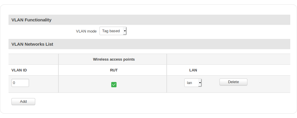
Multiple VLANs can be used through a single Ethernet port. Tags containing the respective VLAN identifiers indicating the VLAN to which the frame belongs are attached to the individual Ethernet frames.
| field name | value | description |
|---|---|---|
| VLAN ID | integer [1..4094]; Default: 1 | VLAN Identification number used for management purposes |
| Wireless access points | yes | no; Default: no | Assigns selected Wi-Fi access point(s) to the selected LAN network |
| LAN | none | lan | custom; Default: lan | Assigns selected LAN ports and wireless access point(s) to a LAN network |
For more a detailed configuration example, check out this article.
LAN Networks
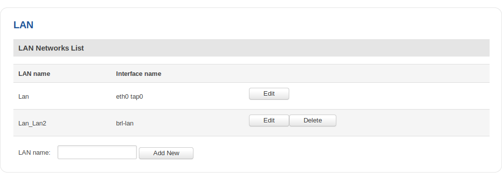
The LAN Networks page provides you with the possibility to create alternate LAN instances that will be used with VLAN. One default instance will be already in place and it will have the configurations from your router's main LAN. Regarding other instances, you can configure everything that you could in the main LAN section, except for the fact that will not be able to use them as the main configuration for your router's LAN.
To create a new LAN instance, type in a name for it in the LAN name field and click the Add New button located next to it. After this you will see that your new instance has appeared in the LAN Networks list. To configure an instance, click the Edit button located next to it. The configuration is identical to regular LAN configuration.


