RUTM08 DNP3
The information in this page is updated in accordance with firmware version RUTM_R_00.07.20.1.
Summary
Distributed Network Protocol 3 (DNP3) is a set of communications protocols used between components in process automation systems. It is primarily used for communications between a client station and Remote Terminal Units (RTUs) or Intelligent Electronic Devices (IEDs).
This manual page provides an overview of the DNP3 functionality in RUTM08 devices.
Note: DNP3 is additional software that can be installed from the System → Package Manager page.
DNP3 Parameters
DNP3 parameters are held within indexes. The index numbers and corresponding system values are described in the table below:
| required value | index | group type |
|---|---|---|
| Uptime | 0 | Counter |
| Hostname | 3 | Octet String |
| Router Serial Number | 5 | Octet String |
| LAN MAC Address | 6 | Octet String |
| Router name | 7 | Octet String |
External Modem Parameters
If you are using an external modem on your device, use these index numbers for corresponding system values:
| required value | index | group type |
|---|---|---|
| Modem VID and PID | 100 + 50 * modem_number | Octet String |
| Mobile data received today (SIM1) | 101 + 50 * modem_number | Counter |
| Mobile data sent today (SIM1) | 102 + 50 * modem_number | Counter |
| Mobile data received this week (SIM1) | 103 + 50 * modem_number | Counter |
| Mobile data sent this week (SIM1) | 104 + 50 * modem_number | Counter |
| Mobile data received this month (SIM1) | 105 + 50 * modem_number | Counter |
| Mobile data sent this month (SIM1) | 106 + 50 * modem_number | Counter |
| Mobile data received last 24h (SIM1) | 107 + 50 * modem_number | Counter |
| Mobile data sent last 24h (SIM1) | 108 + 50 * modem_number | Counter |
| Mobile data received last week (SIM1) | 109 + 50 * modem_number | Counter |
| Mobile data sent last week (SIM1) | 110 + 50 * modem_number | Counter |
| Mobile data received last month (SIM1) | 111 + 50 * modem_number | Counter |
| Mobile data sent last month (SIM1) | 112 + 50 * modem_number | Counter |
| Mobile data received today (SIM2) | 113 + 50 * modem_number | Counter |
| Mobile data sent today (SIM2) | 114 + 50 * modem_number | Counter |
| Mobile data received this week (SIM2) | 115 + 50 * modem_number | Counter |
| Mobile data sent this week (SIM2) | 116 + 50 * modem_number | Counter |
| Mobile data received this month (SIM2) | 117 + 50 * modem_number | Counter |
| Mobile data sent this month (SIM2) | 118 + 50 * modem_number | Counter |
| Mobile data received last 24h (SIM2) | 119 + 50 * modem_number | Counter |
| Mobile data sent last 24h (SIM2) | 120 + 50 * modem_number | Counter |
| Mobile data received last week (SIM2) | 121 + 50 * modem_number | Counter |
| Mobile data sent last week (SIM2) | 122 + 50 * modem_number | Counter |
| Mobile data received last month (SIM2) | 123 + 50 * modem_number | Counter |
| Mobile data sent last month (SIM2) | 124 + 50 * modem_number | Counter |
| Modem temperature (in 0.1 °C) | 125 + 50 * modem_number | Octet String |
| Operator | 126 + 50 * modem_number | Octet String |
| Network state | 127 + 50 * modem_number | Octet String |
| Connection state | 128 + 50 * modem_number | Octet String |
| Signal Strength | 129 + 50 * modem_number | Octet String |
The modem_number of the external modem is 0 (internal modem is skipped).
To get the exact index of a parameter, use the formula in the table above. For example, the index of an external modem operator is 126. Formula is: 126 + 50 * 0.
DNP3 TCP Client
A client in DNP3 is a component that communicates (requests data) with a single outstation via a communication channel. By default, the client list is empty. To add a new client, click the 'Add' button.
After clicking 'Add' you will be redirected to the newly added client's configuration page.
Status
This section displays DNP3 Clients status information.
DNP3 TCP Client Configuration
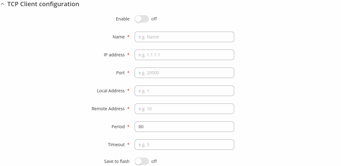
The TCP Client Configuration section is used to configure the parameters of a DNP3 Outstation that the Client (this RUTM08 device) will be querying with requests. The figure below is an example of the TCP Client Configuration and the table below provides information on the fields contained in that section:
| Field | Value | Description |
|---|---|---|
| Enable | off | on; default: off | Turns communication with the outstation device on or off. |
| Name | string; default: none | Name of the TCP client, used for easier management purposes. |
| IP address | ip; default: none | DNP3 Outstation IP address. |
| Port | integer [0..65535]; default: none | DNP3 Outstation Port. |
| Local Address | integer [0..65535]; default: none | Clients Link-Layer address. |
| Remote Address | integer [0..65535]; default: none | Outstation Link-Layer address. |
| Period | integer [1..60]; default: none | Interval at which requests are sent to the outstation device. |
| Timeout | integer [1..60]; default: none | Maximum response wait time. |
| Save to flash | off | on; default: off | When enabled, stores request information in device flash. |
Requests Configuration
A DNP3 request is a way of obtaining data from DNP3 Outstations. The client sends a request to an outstation specifying the function codes to be performed. The outstation then sends the requested data back to the DNP3 client.
The Request Configuration list is empty by default. To add a new Request Configuration look to the Add New Instance section. Enter a custom name into the 'New Configuration Name' field and click the 'Add' button:
The new Request Configuration should become visible in the list:
| Field | Value | Description |
|---|---|---|
| Name | string; default: Unnamed | Name of this Request Configuration. Used for easier management purposes. |
| Start Index | integer [0..65535]; default: none | Start index of the data subarray. |
| End Index | integer [0..65535]; default: none | End index of the data subarray. |
| Data Type | Binary | Double Binary | Counter | Frozen Counter | Analog | Octet String | Analog Output Status | Binary Output Status; default: Binary | Data object group of the requested index(-es). |
| Enabled | off | on; default: off | Turns the request on or off. |
| Actions | - interactive button | Deletes request configuration. |
Request Configuration Testing
This section is used to check whether the configuration works correctly. Simply click the 'Test' button and a response should appear in the box below. The last value represents the configured request data. A successful response to a test may look something like this:
DNP3 Serial Client
The Serial Client page is used to configure the device as a DNP3 RTU Client. DNP3 RTU (remote terminal unit) is a serial communication protocol mainly used in communication via serial interfaces.
By default, the list is empty. To add a new client instance, enter the instance name, select serial interface and click the 'Add' button.
After clicking 'Add' you will be redirected to the newly added client instance configuration page.
Status
This section displays DNP3 Clients status information.
DNP3 Serial Client Configuration
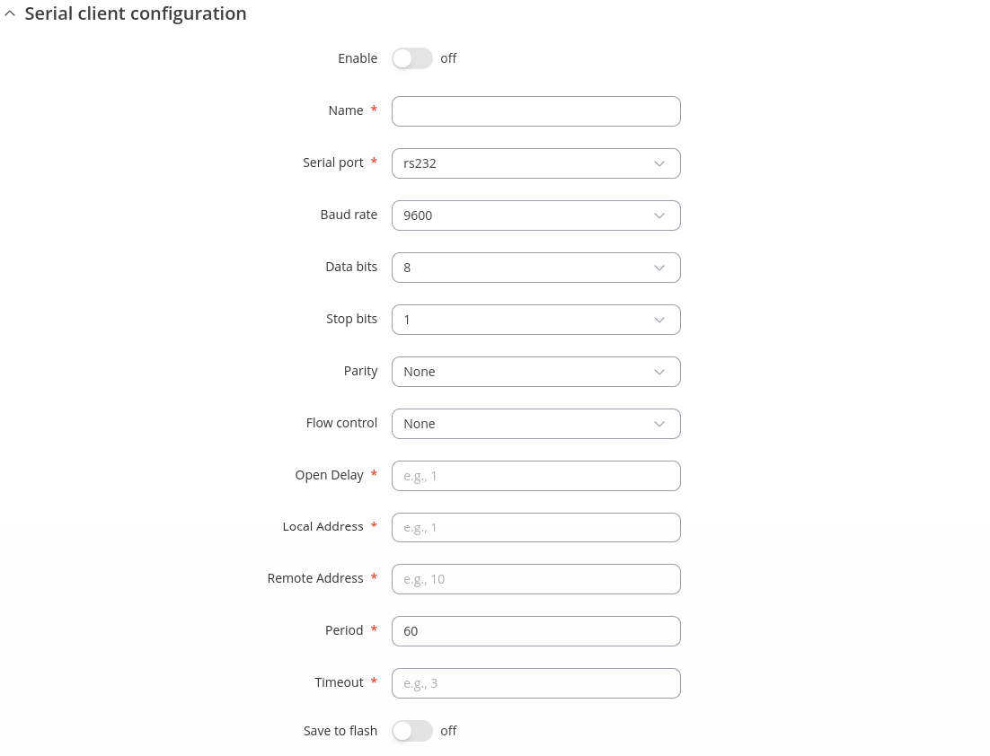
The Serial Client Configuration section is used to configure the parameters of a DNP3 Outstation that the Client (this RUTM08 device) will be querying with requests. The figure below is an example of the Serial Client Configuration and the table below provides information on the fields contained in that section:
| Field | Value | Description |
|---|---|---|
| Enable | off | on; default: off | Turns communication with the outstation device on or off. |
| Name | string; default: none | Name of the Serial client, used for easier management purposes. |
| Serial port | USB RS232 interface; default: USB RS232 interface | Selects which serial port to use for communication. |
| Baud rate (USB) | integer [300..4000000]; default:9600 | Data rate for serial data transmission (in bits per second (bps)). |
| Data bits | 5 | 6 | 7 |8; default: 8 | Number of data bits for each character. |
| Stop bits | 1| 2; default: 1 | Stop bits sent at the end of every character allow the receiving signal hardware to detect the end of a character and to resynchronise with the character stream. Electronic devices usually use one stop bit. Two stop bits are required if slow electromechanical devices are used. |
| Parity | Even | Odd| Mark | Space | None; default: None | In serial transmission, parity is a method of detecting errors. An extra data bit is sent with each data character, arranged so that the number of 1 bits in each character, including the parity bit, is always odd or always even. If a byte is received with the wrong number of 1s, then it must have been corrupted. However, an even number of errors can pass the parity check.
|
| Flow control | None | RTS/CTS | Xon/Xoff; default: None | In many circumstances a transmitter might be able to send data faster than the receiver is able to process it. To cope with this, serial lines often incorporate a "handshaking" method, usually distinguished between hardware and software handshaking.
|
| Open delay | integer [0..10000]; default: none | Some physical layers need time to 'settle' so that the first tx isn't lost. |
| Local Address | integer [0..65535]; default: none | Client Link-Layer address. |
| Remote Address | integer [0..65535]; default: none | Outstation Link-Layer address. |
| Period | integer [1..60]; default: none | Interval at which requests are sent to the outstation device. |
| Timeout | integer [1..60]; default: none | Maximum response wait time. |
| Save to flash | off | on; default: off | When enabled, stores request information in device flash. |
Requests Configuration
A DNP3 request is a way of obtaining data from DNP3 Outstations. The client sends a request to an outstation specifying the function codes to be performed. The outstation then sends the requested data back to the DNP3 client.
The Request Configuration list is empty by default. To add a new Request Configuration look to the Add New Instance section. Enter a custom name into the 'New Configuration Name' field and click the 'Add' button:
The new Request Configuration should become visible in the list:
| Field | Value | Description |
|---|---|---|
| Name | string; default: Unnamed | Name of this Request Configuration. Used for easier management purposes. |
| Start Index | integer [0..65535]; default: none | Start index of the data subarray. |
| End Index | integer [0..65535]; default: none | End index of the data subarray. |
| Data Type | Binary | Double Binary | Counter | Frozen Counter | Analog | Octet String | Analog Output Status | Binary Output Status; default: Binary | Data object group of the requested index(-es). |
| Enabled | off | on; default: off | Turns the request on or off. |
| Actions | - interactive button | Deletes request configuration. |
Request Configuration Testing
This section is used to check whether the configuration works correctly. Simply click the 'Test' button and a response should appear in the box below. The last value represents the configured request data. A successful response to a test may look something like this:
DNP3 Outstation
An outstation in DNP3 is a component that communicates with a single client via a communication channel. It makes measurements of the physical world and then sends them to a client upon request (solicited) or on its own accord (unsolicited). Occasionally a client requests that it do something by sending it a control. This provides the user with the possibility to get system parameters.
General
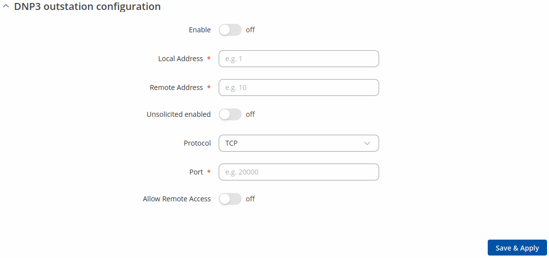
The figure below is an example of the DNP3 Outstation general window section and the table below provides information on the fields contained in that window:
| Field | Value | Description |
|---|---|---|
| Enable | off | on; default: off | Turns DNP3 Outstation on or off. |
| Local Address | integer [0..65535]; default: none | Outstation Link-Layer address. |
| Remote Address | integer [0..65535]; default: none | Client Link-Layer address. |
| Unsolicited enabled | off | on; default: none | Enables the transmission of unsolicited messages. |
| Protocol | TCP | UDP; default: TCP | Protocol used for DNP3 communications. |
| Port | integer [0..65535]; default: none | Port used for DNP3 communications. |
| UDP response address | ipv4; default: none | UDP response address. |
| UDP response port | integer [0..65535]; default: none | UDP response port. |
| Allow Remote Access | off | on; default: off | Allows remote DNP3 connections by adding an exception to the device's firewall on the port specified in the field above. |
Data Sources
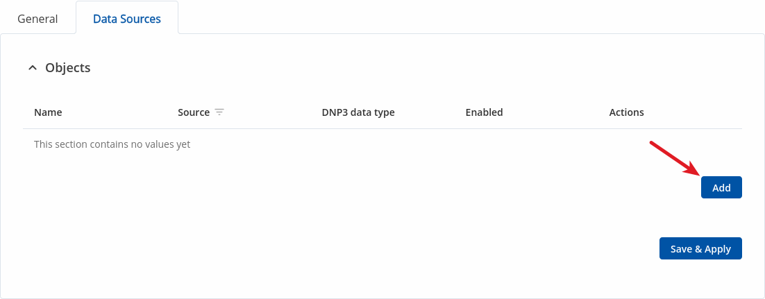
Data sources transmit data from one or more data sources (can be a Modbus client, DNP3 client, M-BUS) and write it to DNP3 objects.
To add new data source, press `Add` button:
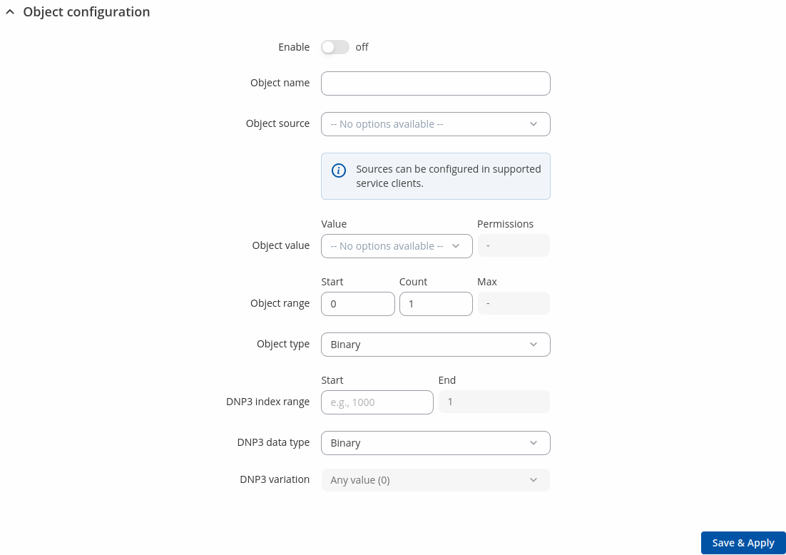
Object configuration:
| Field | Value | Description |
|---|---|---|
| Enable | off | on; default: off | Turns Object configuration on or off. |
| Object name | string; default: none | Name of the object. |
| Object source | list; default: none | Client service which will be sending requests. |
| Object value | list and permissions type; default: none | Request value and its permissions (Read-Only, Write-Only or Read-Write). |
| Object range | integer [1..65535]; default: none | Specify the start index and count for the range. |
| Object type | Binary | String | Bool | INT8 | UINT8 | INT16 | UINT16 | INT32 | UINT32 | INT64 | UINT64 | FLOAT32 | FLOAT64; default: Binary | Value data type. |
| DNP3 index range | integer; default: none | Start and calculated end index. |
| DNP3 data type | Binary | Double Binary | Binary Output | Counter; default: Binary | Available data types for the selected value. |
| DNP3 variation | DNP3 data type variation. |
DNP3 Serial Outstation
An outstation in DNP3 is a component that communicates with a single client via a communication channel. It makes measurements of the physical world and then sends them to a client upon request (solicited) or on its own accord (unsolicited). Occasionally a client requests that it do something by sending it a control. This provides the user with the possibility to get system parameters.
General
General status section displays DNP3 Outstation general status information.
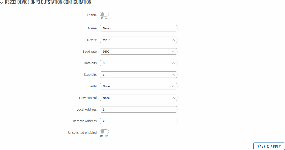
The DNP3 Serial Outstation configuration section is used to configure the parameters of a Serial DNP3 Outstation that will be queried by other Client devices. The figure below is an example of the Serial Outstation Configuration and the table below provides information on the fields contained in that section. By default, the list is empty. To add a new outstation instance, enter the instance name, select serial interface and click the 'Add' button.
| Field | Value | Description |
|---|---|---|
| Enable | off | on; default: off | Turns communication with the outstation device on or off. |
| Name | string; default: none | Name of the Serial outstation, used for easier management purposes. |
| Serial port | USB RS232 interface; default: USB RS232 interface | Selects which serial port to use for communication. |
| Baud rate (USB) | integer [300..4000000]; default:9600 | Data rate for serial data transmission (in bits per second (bps)). |
| Data bits | 5 | 6 | 7 |8; default: 8 | Number of data bits for each character. |
| Stop bits | 1| 2; default: 1 | Stop bits sent at the end of every character allow the receiving signal hardware to detect the end of a character and to resynchronise with the character stream. Electronic devices usually use one stop bit. Two stop bits are required if slow electromechanical devices are used. |
| Parity | Even | Odd| Mark | Space | None; default: None | In serial transmission, parity is a method of detecting errors. An extra data bit is sent with each data character, arranged so that the number of 1 bits in each character, including the parity bit, is always odd or always even. If a byte is received with the wrong number of 1s, then it must have been corrupted. However, an even number of errors can pass the parity check.
|
| Flow control | None | RTS/CTS | Xon/Xoff; default: None | In many circumstances a transmitter might be able to send data faster than the receiver is able to process it. To cope with this, serial lines often incorporate a "handshaking" method, usually distinguished between hardware and software handshaking.
|
| Local Address | integer [0..65535]; default: none | Outstation Link-Layer address. |
| Remote Address | integer [0..65535]; default: none | Client Link-Layer address. |
| Unsolicited enabled | off | on; default: none | Enables the transmission of unsolicited messages. |
Data Sources
Data sources transmit data from one or more data sources (can be a Modbus client) and write it to DNP3 objects.
To add new data source, press `Add` button (Note: DNP3 serial outstation instance is required when creating a new instance.):
Object configuration:
| Field | Value | Description |
|---|---|---|
| Enable | off | on; default: off | Turns Object configuration on or off. |
| Object name | string; default: none | Name of the object. |
| Object source | list; default: none | Client service which will be sending requests. |
| Object value | list and permissions type; default: none | Request value and its permissions (Read-Only, Write-Only or Read-Write). |
| Object range | integer; default: none | Specify the start index and count for the range. |
| Object type | Binary | String | Bool | INT8 | UINT8 | INT16 | UINT16 | INT32 | UINT32 | INT64 | UINT64 | FLOAT32 | FLOAT64; default: Binary | Value data type. |
| DNP3 index range | integer; default: none | Start and calculated end index. |
| DNP3 data type | Binary | Double Binary | Binary Output | Counter; default: Binary | Available data types for the selected value. |
| DNP3 variation | DNP3 data type variation. |


