RUTX10 Failover
The information in this page is updated in accordance with firmware version RUTX_R_00.07.20.1.
Summary
This chapter is an overview of the Failover, VRRP functions in RUTX10 device.
Note: Failover is additional software on some devices that can be installed from the System → Package Manager page.
Failover
The Failover function allows you to backup your primary WAN connection in case it goes down.
In order to set priorities, just change the interface metrics in the `Interfaces` section and then press Save & Apply.
Note: You will not see any extra wired wan interfaces unless you have LAN ports configured as WAN.
Interfaces with higher metrics on the list have a higher priority than the ones that are with lower metrics, i.e., the device will always use the WAN interface with the highest metric as long as it is available. If it goes down, the device will start using the interface with the second highest metric and so on.
Take note that changing an interface's metrics in the list here also changes its position in the following pages:
- Network → WAN
Load Balancing
Load Balancing is a method of dividing traffic between multiple WAN interfaces. Load Balancing can be used to share the data load between different interfaces and increase the overall Internet speed for multiple users and connections. It is important to note that Load Balancing does not increase speed for any single connection. For example, if you're downloading a large file, using Load Balancing will not increase the speed of that download.
However, Load Balancing can be used to increase the speed of multiple connections. For example, when used in a WiFi network, Load Balancing would utilize the resources of multiple WAN interfaces to handle the many various requests of different clients.
Both Load Balancing and Failover cannot be used at the same time. If you wish to select Load Balancing, you can do that in the dropdown located under 'Settings' section:
When Load Balancing is selected, you can assign Weight values to WAN interfaces. The value represents a percentage of traffic load that will go through an interface. For example, if you set it up like this:
|
3 |
|
2 |
then about 60 % (3/5) of traffic would go through the Wired WAN interface and about 40 % (2/5) would go through WiFi WAN. In this case if you played 100 different videos on the Internet, about 60 would be downloaded through Wired WAN and the other 40 would be downloaded via WiFi WAN.
Interface
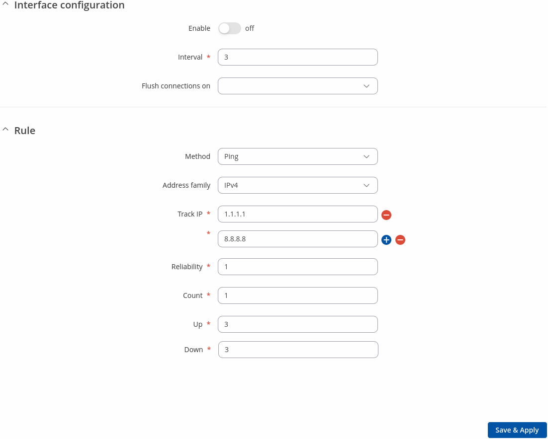
A Interface page is used to configure how the device will determine whether an interface is online or offline. To enter an interface configuration page, click the 'Edit' button next to an interface.
After this you should be redirected to the configuration page of that interface.
| Field | Value | Description |
|---|---|---|
| Enable | off | on; default: off | Turn the interface on or off. |
| Interval | integer [1..65000]; default: 3 | Number of seconds between each test |
| Flush connections on | Connected | Disconnected | Interface up | Interface down: none | Flushes established connections after the selected scenario occurs to renew the priorities of configured interfaces.
|
| Method | Ping | Wget; default: Ping | Defines how health check will be performed on this interface when determining its state. |
| Track IP | ip | hostname; default: 1.1.1.1,8.8.8.8 | IP address(es) or hostname(s) that will be used to determine an interface's state. If the device receives no response from any of the specified hosts, the interface will be considered as 'Offline'. If this value is missing the interface is always considered up. |
| Reliability | integer [1..65000]; default: 1 | Number of hosts that must reply for the test to be considered successful. Make sure there are at least this many hosts defined in the 'Track IP' field, otherwise the interface will always be considered as 'Offline'. |
| Count | integer [1..65000]; default: 1 | Number of pings to send to each host with each test. |
| Up | integer [1..65000]; default: 3 | Number of successful tests required to considered an interface as 'Online'. |
| Down | integer [1..65000]; default: 3 | Number of failed tests required to considered an interface as 'Offline'. |
Member
The Member page is for editing/creating a list of members and assigning interfaces to them. You can also set metrics for each user (this will be used for Failover) or weights for each member (this will be used for Load balancing).
| Field | Value | Description |
|---|---|---|
| Name | string; default: | Name of the member. |
| Interface | Name of the interface; default: | List of available interfaces (depends on the device) |
| Metric | integer; default: 1 | Members within one policy with a lower metric have precedence over higher metric members. Members with the same metric within a policy will perform load balancing. |
| Weight | integer; default: 1 | The weight values represent a percentage of load that will go through an interface. The default value is 1, if unspecified. |
| Actions | -(interactive button); default: Delete | Removes a member. |
Policy
A Policy dictates what the the device should do when some network traffic matches the condition defined in a Failover/Load Balancing rule. There are two policies by default, one for Load Balancing (balance), the other for Failover (mwan). You may create custom policies that use different interfaces for Failover/Load Balancing scenarios.
| Field | Value | Description |
|---|---|---|
| Member used | list from members page; default: none | Members assigned to the policy. |
| Last Resort | Unreachable | Blackhole | Default; default: Unreachable | Determine the fallback routing behaviour if all WAN members in the policy are down.
|
Rule
A Load Balancing/Failover Rule is a set of conditions that define some type of network traffic. The traffic that matches the conditions set in the rule is handled in accordance to the specified Policy.
There is one default rule present on the device. You can add more rules with the 'Add' button or you can customize the existing rule by clicking the 'Edit' button next to it:
| Field | Value | Description |
|---|---|---|
| Name | string; default: default | Name of the rule. |
| Protocol | all | tcp | udp | icmp | esp; default: all | Protocol to match this rule. |
| Source address | ip/netmask; default: none | Source IP addresses to match this rule. |
| Destination address | ip/netmask; default: 0.0.0.0/0 | Destination IP addresses to match this rule. |
| Sticky | off | on; default: off | If turned on, traffic from the same source IP address that previously matched this rule within the sticky timeout period will use the same WAN interface. |
| Sticky timeout | integer [1..1000000]; default: none | Timeout in seconds. |
| Policy assigned | default (Load Balancing) | default (Failover) | Unreachable (Reject) | Blackhole (Drop) | Default (Use main routing table) | custom; default: default (Failover) | Specifies the policy applied to matching traffic. |
VRRP
Summary
Virtual Router Redundancy Protocol (VRRP) is a computer networking protocol used for automatic default gateway selection for clients on a LAN network in case the main router (Master) becomes unavailable. Another VRRP router (Backup) then assumes the role of Master; thus backing up the connection.
This page is an overview of the VRRP section of RUTX10 devices.
VRRP Configuration
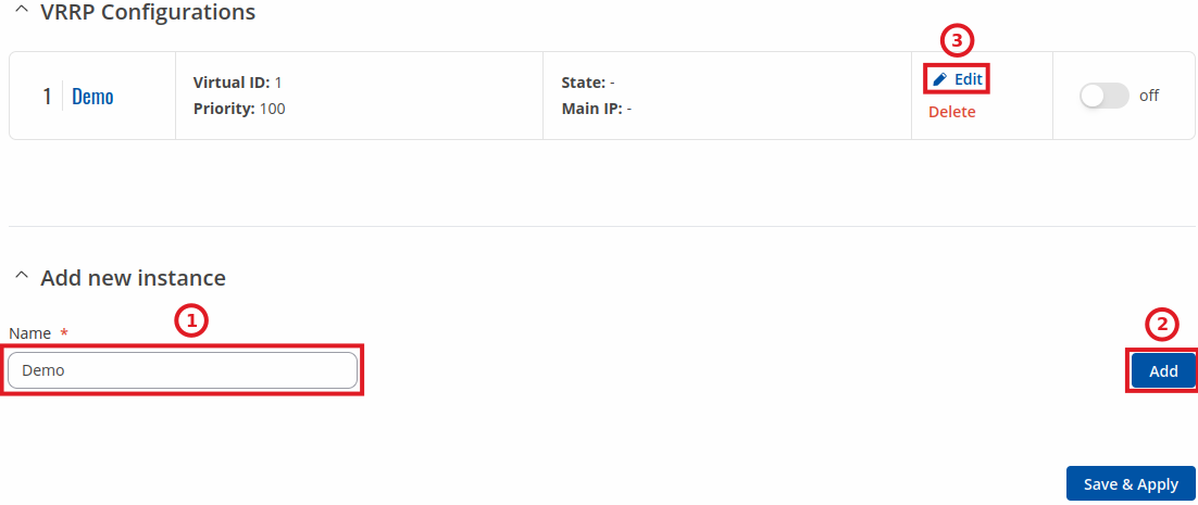
The VRRP Configuration section lists VRRP instances currently existing on the device. By default the list is empty thus, you must first create at least one instance in order to begin configuring VRRP.
- Enter a custom name for the new VRRP configuration in the 'Name' field.
- Click the 'Add' button.
- Click the 'Edit' button next to the newly created instance.
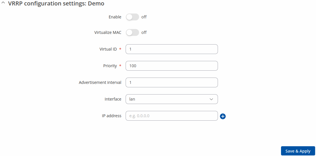
After clicking the 'Edit' button you should be redirected to that VRRP instance's configuration page, which should look similar to this:
| Field | Value | Description |
|---|---|---|
| Enable | off | on; default: off | Turns VRRP on or off. |
| Virtualize MAC | off | on; default: off | Turns the possibility to use virtual MAC addresses on or off. |
| Virtual ID | integer [1..255]; default: 1 | The Virtual Router Identifier (VRID) is a field in the VRRP packet IP header used to identify the virtual router in the VRRP cluster. Routers with identical IDs will be grouped in the same VRRP cluster. |
| Priority | integer [1..255]; default: 100 | VRRP priority of the virtual router. Higher values equal higher priority. The router with the highest priority is considered to be the Master router while other routers are Backup routers.
|
| Advertisement interval | integer [1..255]; default: 100 | Time interval (in seconds) between router advertisements on the VRRP network. |
| Interface | network interface; default: LAN | Selects which interface VRRP will operate on. |
| IP address | ip; default: none | Virtual IP address for the router's VRRP cluster. |
Check connection
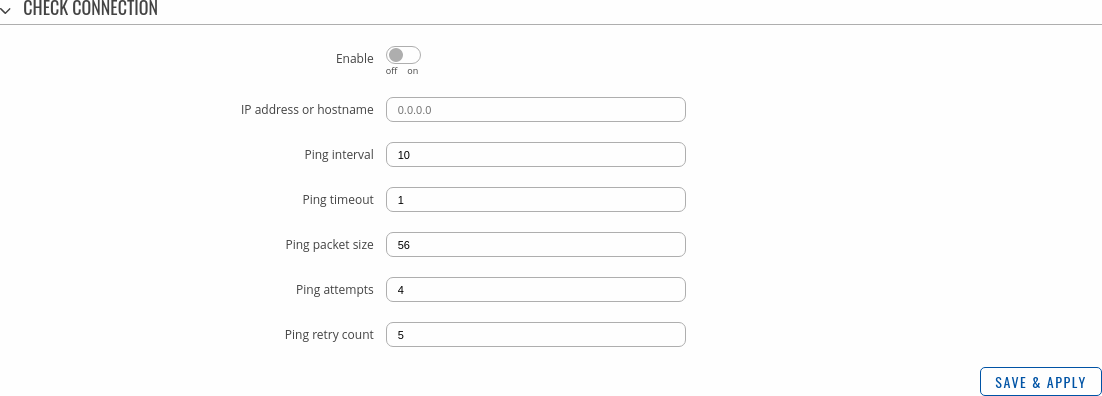
The Check connection section is used to set the parameters that define how the router will determine whether the connection is still available or not. This is done by periodically sending ICMP packets from interface, configured in VRRP Configuration section, to a defined host and awaiting responses. If no response is received after a defined period of time, the connection is determined to be down, and thus the role of Master is assumed by another router in the network.
Refer to the figure and table below for information on the fields contained in the Check connection section.
| Field | Value | Description |
|---|---|---|
| Enable | yes | no; default: no | Turns connection checking on or off. |
| IP address or hostname | ip | host; default: none | IP address or hostname to which the router will send ICMP packets. This is used to determine whether the connection is still available or not. ICMP packets will be send from interface, configured in VRRP Configuration section, therefore make sure you enter reachable IP address or hostname. |
| Ping interval | integer; default: 10 | Time interval (in seconds) between two pings. |
| Ping timeout | integer; default: 1 | The maximum amount of time in seconds the router will wait for a response to a ping request. If it does not receive a response within the amount of time defined in this field, the ping request will be considered to have failed. |
| Ping packet size | integer; default: 56 | The size (in bytes) of sent ICMP packets. |
| Ping attempts | integer; default: 4 | Number of ping packets sent. |
| Ping retry count | integer; default: 5 | How many times the router will retry sending ping requests before determining that the connection has failed. |


