Setting up a GRE tunnel between RUT and Cisco device via Cisco CLI
Introduction
Generic Routing Encapsulation (GRE) is a tunneling protocol that can encapsulate a wide variety of network layer protocols inside virtual point-to-point links over an Internet Protocol network.
This article provides an extensive configuration example with details on how to create a tunnel connection between two GRE Tunnel instances, one of which is configured on RUTxxx router and the second one on Cisco device using CLI.
Prerequisites
You will need:
- One RUTxxx router
- One Cisco router (this configuration example was created using Cisco ISR4321 Router)
- A PC to configure the routers
- PuTTy or similiar terminal program
- Both routers must have a Public Static or Public Dynamic IP addresses
Configuration scheme
Cisco configuration
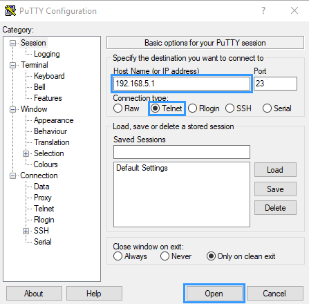
First, open PuTTY, and connect to router, enter routers LAN IP (in this example - 192.168.5.1), choose connection type, we are using Telnet, and press Open. Then depending on your router you might need to enter username and password in terminal.
After you are connected, create and configure GRE tunnel interface:
To enter configuration mode, execute command:
GRE_Cisco#configure terminal
Then execute following commands:
 GRE_Cisco(config)# interface Tunnel0
 GRE_Cisco(config-if)# ip address 172.16.0.2 255.255.255.0 # GRE Tunnel IP address and mask
 GRE_Cisco(config-if)# ip mtu 1400
 GRE_Cisco(config-if)# ip tcp adjust-mss 1360
 GRE_Cisco(config-if)# tunnel source 84.x.x.2 # CISCO side WAN IP
 GRE_Cisco(config-if)# tunnel destination 8.x.x.1 # RUT Side WAN IP
 GRE_Cisco(config-if)# exit
To add route to RUT‘s local network execute:
GRE_Cisco(config)# ip route 192.168.1.0 255.255.255.0 172.16.0.1
With this, if you followed steps correctly Cisco Routers configuration should be finished.
RUT configuration
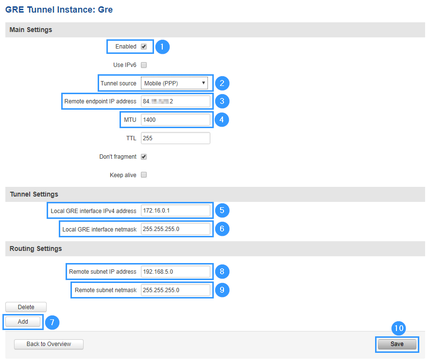
Connect to router's WebUI, go to Services > VPN > GRE Tunnel. Enter a name for your GRE instance, click ADD and when instance appears in GRE Configuration field, click Edit.
Then apply the configuration presented below:
- Enable instance.
- Sellect Tunnel source (here we are using Mobile (PPP) connection).
- Enter Remote endpoint IP address (Public IP of Cisco router).
- Change MTU value to 1400 (it was set in Cisco router using this command: GRE_Cisco(config-if)# ip mtu 1400).
- Set Local GRE interface IPv4 address to 172.16.0.1
- Enter Local GRE interface netmask - 255.255.255.0
- When creating new GRE interface you will first have to press Add in Routing Settings before entering following information.
- Enter Remote subnet IP address - 192.168.5.0
- Enter Remote subnet netmask - 255.255.255.0
- Press Save
Testing configuration
If all steps were followed correctly, tunnel interface should be active. But as with any other configuration, it is always wise to test the setup in order to make sure that it works properly. In order to test the GRE Tunnel connection, login to RUT WebUI and go to Services → CLI. Login with user name: root and the router's admin password. From there you should then be able to ping the opposite instance's virtual IP address. To use a ping command, type ping <Cisco_ip_address> and press the "Enter" key on your keyboard. You can also check it form Cisco routers side, connect to router with PuTTy or equivalent program and use same ping command ping <RUT_ip_address>.
If ping requests are working, yours setup ready to use! If not please review the steps in this example once more.


