TRB256 BACnet
The information in this page is updated in accordance with firmware version TRB2M_R_00.07.20.1.
Summary
BACnet is a communication protocol for building automation and control (BAC) networks that use the ASHRAE, ANSI, and ISO 16484-5 standards protocol.
This manual page provides an overview of the BACnet functionality in TRB256 devices.
Note: BACnet is additional software that can be installed from the System → Package Manager page.
General Configuration
| Field | Value | Description |
|---|---|---|
| Enable | off | on; default: off | Enables BACnet router function. |
| Enable BBMD | off | on; default: off | Enables BACnet broadcast management function. |
| BBMD port | integer [1..65535]; default: 47808 | BACnet broadcast management devices port. |
| BBMD interface | network interface; default: br-lan | Specifies interface for BBMD function. IP address of this interface should be reachable from WAN. |
| Allow Remote Access | off | on; default: off | Creates port forward firewall rule to make application port in LAN reachable from selected BBMD interface. |
| Force gateway | off | on; default: off | Adds configured gateway IP address and port to BBMD packages sent. |
| Gateway address | ip4; default: none | Gateway IP address. |
| Gateway port | integer [1..65535]; default: none | Gateway port number. |
BDT Configuration
This section contains Broadcast Distribution Table (BDT) configuration, where you specify the list of BBMDs (BACnet Broadcast Management Devices) responsible for forwarding broadcast messages between different subnets in a BACnet/IP network.
| Field | Value | Description |
|---|---|---|
| IP address | ipv4; default: none | IP addresses of the BBMDs in the network. |
| Port | integer [1..65535]; default: none | Port numbers on which the BBMDs listen for BACnet/IP messages. |
| Netmask | netmask; default: none | Subnet masks used by the BBMDs to determine the range of IP addresses within a subnet. |
| Actions | -interactive button; default: delete | Deletes BDT configuration. |
BIP Configuration
Communications in BACnet over IP (BIP) rely upon the protocol rules of IP and Ethernet.
| Field | Value | Description |
|---|---|---|
| Network ID | integer [1..65535]; default: 1 | Unique identifier for the BACnet/IP subnet within the entire BACnet internetwork. |
| Port | integer [1..65535]; default: 47808 | This specifies the port number used by BACnet/IP devices for communication. |
| Device | interface; default: br-lan | Select the network device to be used for BACnet/IP communication. |
| Actions | -interactive button; default: delete | Deletes BIP configuration. |
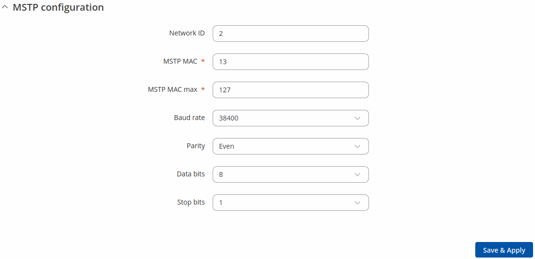
MSTP Configuration
MSTP is most commonly used to connect field devices to controllers / routers / control applications. The physical layer uses RS485 which allows up to 31 devices to be installed on a single network.
| Field | Value | Description |
|---|---|---|
| Network ID | integer [1..65535]; default: 2 | Unique identifier for the BACnet MSTP network. |
| MSTP MAC | integer [0..127]; default: 13 | Router MSTP MAC address. |
| MSTP MAC max | integer [1..127]; default: 127 | Maximum client address in the MSTP network. |
| Baud rate | 300 | 600 | 1200 | 2400 | 4800 | 9600 | 19200 | 38400 | 57600 | 115200 | 230400| 460800 | 921600 | 1000000 | 3000000; default: 38400 | Serial data transmission rate (in bits per second). |
| Parity | Even | Odd | Mark | Space | None; default: None | In serial transmission, parity is a method of detecting errors. An extra data bit is sent with each data character, arranged so that the number of 1 bits in each character, including the parity bit, is always odd or always even. If a byte is received with the wrong number of 1s, then it must have been corrupted. However, an even number of errors can pass the parity check.
|
| Data bits | 7 | 8; default: 8 | Number of data bits for each character. |
| Stop bits | 1 | 2; default: 1 | Stop bits sent at the end of every character allow the receiving signal hardware to detect the end of a character and to resynchronise with the character stream. Electronic devices usually use one stop bit. Two stop bits are required if slow electromechanical devices are used.. |


