Policy Based Routing: Difference between revisions
| (41 intermediate revisions by 2 users not shown) | |||
| Line 1: | Line 1: | ||
<p style="color:red">The information on this page is updated in accordance with the [https://wiki.teltonika-networks.com/view/FW_%26_SDK_Downloads'''00.07.07.1'''] firmware version .</p> | <p style="color:red">The information on this page is updated in accordance with the [https://wiki.teltonika-networks.com/view/FW_%26_SDK_Downloads'''00.07.07.1'''] firmware version.</p> | ||
==Introduction== | ==Introduction== | ||
Policy-based routing (PBR) is a technique used in computer networking to direct network packets based on defined criteria beyond the standard destination-based routing. Unlike traditional routing, which forwards packets solely based on their destination address, PBR allows to customize routing decisions according to various factors. | Policy-based routing (PBR) is a technique used in computer networking to direct network packets based on defined criteria beyond the standard destination-based routing. Unlike traditional routing, which forwards packets solely based on their destination address, PBR allows to customize routing decisions according to various factors. | ||
With policy-based routing can implement specific rules or policies to dictate the path that packets should take through the network. This flexibility enables organizations to optimize traffic flow, prioritize certain types of traffic, enforce security measures, and manage network resources more efficiently. | With policy-based routing you can implement specific rules or policies to dictate the path that packets should take through the network. This flexibility enables organizations to optimize traffic flow, prioritize certain types of traffic, enforce security measures, and manage network resources more efficiently. | ||
==Prerequisites & Topology== | ==Prerequisites & Topology== | ||
'''Before proceeding with the | |||
'''Before proceeding with the configuration, ensure that all requirements are met:''' | |||
# Before starting you need to have 3 different WAN connections. In this case we are going to use: '''[https://wiki.teltonika-networks.com/view/WiFi_WAN_example Wi-fi WAN]''', '''Wired WAN''' and '''Mobile WAN'''.These interfaces have to be preconfigured. | # Before starting you need to have 3 different WAN connections. In this case we are going to use: '''[https://wiki.teltonika-networks.com/view/WiFi_WAN_example Wi-fi WAN]''', '''Wired WAN''' and '''Mobile WAN'''.These interfaces have to be preconfigured. | ||
[[File: | [[File:698722_1_1.png|border|class=tlt-border|center| 1000x1000px]] | ||
==Configuration== | ==Configuration== | ||
{{Template:Networking_rutos_manual_basic_advanced_webui_disclaimer | {{Template:Networking_rutos_manual_basic_advanced_webui_disclaimer | ||
| series = RUTX | | series = RUTX | ||
| Line 45: | Line 45: | ||
Make the following changes: | Make the following changes: | ||
# Enter Name : '''LAN_VLAN_ETH0''' | # Enter Name : '''LAN_VLAN_ETH0''' | ||
[[File:PBS LAN1 | # Enter IPV4 address: '''192.168.100.1''' | ||
# Select IPV4 netmask: '''255.255.255.0''' | |||
[[File:PBS LAN1 NAME1111.png|border|class=tlt-border|center]] | |||
====LAN1 Physical Settings==== | ====LAN1 Physical Settings==== | ||
| Line 91: | Line 93: | ||
After configuring all LAN interfaces the end result should look something like this: | After configuring all LAN interfaces the end result should look something like this: | ||
[[File:PBS | [[File:PBS LAN_CON1.png|border|class=tlt-border|center| 1100x370px]] | ||
===Configuring Policy Based Routing=== | ===Configuring Policy Based Routing=== | ||
---- | ---- | ||
Open WebUI → Network → Routing → Policy based routing → Add new instance and create new instances for each available WAN in this case Wi-Fi WAN, Wired-WAN and Mobile: | Open '''WebUI → Network → Routing → Policy based routing → Add new instance''' and create new instances for each available WAN in this case Wi-Fi WAN, Wired-WAN and Mobile: | ||
====Creating Wifi Wan Routing Table==== | ====Creating Wifi Wan Routing Table==== | ||
| Line 107: | Line 109: | ||
=====Static IPv4 Routes===== | =====Static IPv4 Routes===== | ||
---- | ---- | ||
click [[File:Add Button.png|40x70px]] and | click [[File:Add Button.png|40x70px]] and apply this to the route: | ||
#Select Interface: '''WifiWan''' | Enter Target: '''0.0.0.0''' | Enter IPv4-Netmask: '''0.0.0.0''' | Enter IPv4-Gateway: '''192.168.1.1 (Note: Use the Wi-Fi network's gateway. The current LAN gateway in use is 192.168.100.1. However, the correct gateway to route correctly will be the next hop address. This means the router gateway providing the Wi-Fi WAN should be used. In my case, this gateway is 192.168.1.1.)''' | #Select Interface: '''WifiWan''' | Enter Target: '''0.0.0.0''' | Enter IPv4-Netmask: '''0.0.0.0''' | Enter IPv4-Gateway: '''192.168.1.1 (Note: Use the Wi-Fi network's gateway. The current LAN gateway in use is 192.168.100.1. However, the correct gateway to route correctly will be the next hop address. This means the router gateway providing the Wi-Fi WAN should be used. In my case, this gateway is 192.168.1.1.)''' | ||
[[File:PBR_P_ROUTE_111.png|border|class=tlt-border|center|1000x300px]] | [[File:PBR_P_ROUTE_111.png|border|class=tlt-border|center|1000x300px]] | ||
| Line 120: | Line 122: | ||
=====Static IPv4 Routes===== | =====Static IPv4 Routes===== | ||
---- | ---- | ||
click [[File:Add Button.png|40x70px]] and | click [[File:Add Button.png|40x70px]] and apply this to the route: | ||
#Select Interface: ''' | #Select Interface: '''Wan''' | Enter Target: '''0.0.0.0''' | Enter IPv4-Netmask: '''0.0.0.0''' | Enter IPv4-Gateway: '''192.168.10.1''' | ||
[[File: | [[File:PBR_P_ROUTE_222.png|border|class=tlt-border|center|1000x300px]] | ||
====Creating Mobile Wan Routing Table==== | ====Creating Mobile Wan Routing Table==== | ||
| Line 136: | Line 138: | ||
---- | ---- | ||
click [[File:Add Button.png|40x70px]] and | click [[File:Add Button.png|40x70px]] and apply this to the route: | ||
#Select Interface:'''mob1s1a1''' | Enter Target: | #Select Interface:'''mob1s1a1''' | Enter Target: '''0.0.0.0''' | Enter IPv4-Netmask: '''0.0.0.0''' | ||
[[File:PBS_TABLES_WAN.png|border|class=tlt-border|center|1000x300px]] | [[File:PBS_TABLES_WAN.png|border|class=tlt-border|center|1000x300px]] | ||
| Line 177: | Line 179: | ||
---- | ---- | ||
Connect end device to physical port that is assingned to different routing policy. Open cmd and run this command: '''tracert 8.8.8.8''', three physical ports that we assigned to diffrent Vlans route to 8.8.8.8 should be using different gateways and public addresses visit to check if address changes [https://whatismyipaddress.com/ whatismyipaddress]. | Connect end device to physical port that is assingned to different routing policy. Open cmd and run this command: '''tracert 8.8.8.8''', three physical ports that we assigned to diffrent Vlans route to 8.8.8.8 should be using different gateways and public addresses visit to check if address changes [https://whatismyipaddress.com/ whatismyipaddress]. | ||
Public IP addresses that are used in my topology: | |||
# WiFi WAN: '''78.xxx.xxx.xxx''' | |||
# Wired WAN: '''213.xxx.xxx.xxx''' | |||
# Mobile WAN: '''84.xxx.xxx.xxx''' | |||
| Line 183: | Line 190: | ||
---- | ---- | ||
[[File:Test1.png|border|class=tlt-border|center]] | [[File:Test1.png|border|class=tlt-border|center]] | ||
[[File:ISP1.png|border|class=tlt-border|center|800x600px]] | |||
====Physical Port 2 Test Result==== | ====Physical Port 2 Test Result==== | ||
---- | ---- | ||
[[File:Test22.png|border|class=tlt-border|center]] | [[File:Test22.png|border|class=tlt-border|center]] | ||
[[File:ISP2.png|border|class=tlt-border|center|800x600px]] | |||
====Physical Port 3 Test Result==== | ====Physical Port 3 Test Result==== | ||
---- | ---- | ||
[[File:Test33.png|border|class=tlt-border|center]] | [[File:Test33.png|border|class=tlt-border|center]] | ||
[[File:ISP3.png|border|class=tlt-border|center|800x600px]] | |||
===Policy Based Routing on a single Host=== | ===Policy Based Routing on a single Host=== | ||
---- | ---- | ||
====Single Host Routing Topology==== | ====Single Host Routing Topology==== | ||
[[File: | [[File:698721_2_2.png|border|class=tlt-border|center|1000x1000px]] | ||
====Wired WAN Routing Policy Priority Change==== | ====Wired WAN Routing Policy Priority Change==== | ||
| Line 212: | Line 224: | ||
=====Creating Single Node Routing Table Over WifiWan===== | =====Creating Single Node Routing Table Over WifiWan===== | ||
---- | |||
Add new instance: | Add new instance: | ||
| Line 223: | Line 236: | ||
=====Static IPv4 Routes===== | =====Static IPv4 Routes===== | ||
---- | ---- | ||
click [[File:Add Button.png|40x70px]] and | click [[File:Add Button.png|40x70px]] and apply this to the route: | ||
#Select Interface: '''WifiWan''' | Enter Target: '''0.0.0.0''' | Enter IPv4-Netmask: '''0.0.0.0''' | Enter IPv4-Gateway: '''192.168.1.1''' | #Select Interface: '''WifiWan''' | Enter Target: '''0.0.0.0''' | Enter IPv4-Netmask: '''0.0.0.0''' | Enter IPv4-Gateway: '''192.168.1.1''' | ||
[[File:PBR_P_ROUTE_111.png|border|class=tlt-border|center|1000x300px]] | [[File:PBR_P_ROUTE_111.png|border|class=tlt-border|center|1000x300px]] | ||
| Line 244: | Line 257: | ||
---- | ---- | ||
[[File:POLICY_ROUTE.png|border|class=tlt-border|center]] | [[File:POLICY_ROUTE.png|border|class=tlt-border|center]] | ||
[[File:ISP1.png|border|class=tlt-border|center|800x600px]] | |||
==External links== | |||
#https://wiki.teltonika-networks.com/view/Splitting_Network_Traffic_Via_Multiple_Interfaces | |||
Latest revision as of 12:56, 8 July 2024
The information on this page is updated in accordance with the 00.07.07.1 firmware version.
Introduction
Policy-based routing (PBR) is a technique used in computer networking to direct network packets based on defined criteria beyond the standard destination-based routing. Unlike traditional routing, which forwards packets solely based on their destination address, PBR allows to customize routing decisions according to various factors.
With policy-based routing you can implement specific rules or policies to dictate the path that packets should take through the network. This flexibility enables organizations to optimize traffic flow, prioritize certain types of traffic, enforce security measures, and manage network resources more efficiently.
Prerequisites & Topology
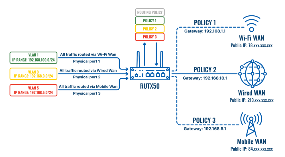
Before proceeding with the configuration, ensure that all requirements are met:
- Before starting you need to have 3 different WAN connections. In this case we are going to use: Wi-fi WAN, Wired WAN and Mobile WAN.These interfaces have to be preconfigured.
Configuration
If you're having trouble finding this page or some of the parameters described here on your device's WebUI, you should turn on "Advanced WebUI" mode. You can do that by clicking the "Advanced" button, located at the top of the WebUI.
Configuring VLANs
Open router‘s WebUI and navigate to Network → VLAN → Port Based configuration:
Port based VLAN
Add new VLANs by clicking ![]() and Make following changes:
and Make following changes:
- VLAN ID: 1 | lan1: Untagged | Lan2: Off | Lan3: Off | lan4: Untagged | Wan: Off
- VLAN ID: 3 | lan1: Off | Lan2: Untagged | Lan3: Off | lan4: Off | Wan: Off
- VLAN ID: 5 | lan1: Off | Lan2: Off | Lan3: Untagged | lan4: Off | Wan: Off

Configuring Different LAN Networks
Open router’s WebUI → Network → LAN click ![]() on current available LAN interface configuration:
on current available LAN interface configuration:
LAN1 General Settings
Make the following changes:
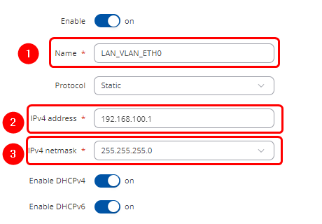
- Enter Name : LAN_VLAN_ETH0
- Enter IPV4 address: 192.168.100.1
- Select IPV4 netmask: 255.255.255.0
LAN1 Physical Settings
Make the following changes:
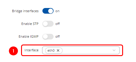
- Select Interface : eth0
Add new LAN netwrok by clicking ![]() and Make following changes:
and Make following changes:
LAN2 General Settings
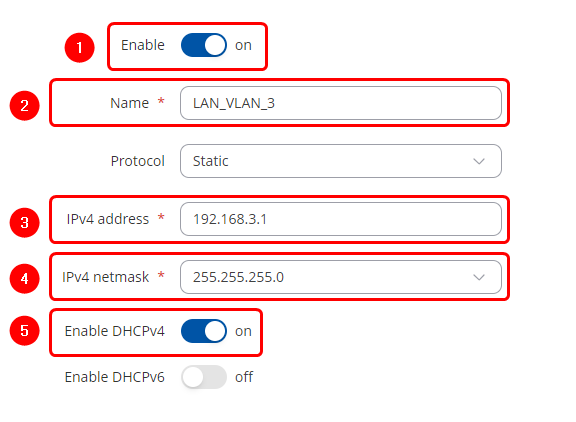
Make the following changes:
- Enable Interface: on
- Enter Name : LAN_VLAN_3
- Enter IPV4 address: 192.168.3.1
- Select IPV4 netmask: 255.255.255.0
- Enable DHCPv4: on
LAN2 Physical Settings
Make the following changes:
- Select Interface : eth0.3

Add new LAN netwrok by clicking ![]() and Make following changes:
and Make following changes:
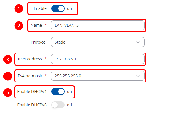
LAN3 General Settings
Make the following changes:
- Enable Interface: on
- Enter Name : LAN_VLAN_5
- Enter IPV4 address: 192.168.5.1
- Select IPV4 netmask: 255.255.255.0
- Enable DHCPv4: on
LAN3 Physical Settings
Make the following changes:
- Select Interface : eth0.5

After configuring all LAN interfaces the end result should look something like this:

Configuring Policy Based Routing
Open WebUI → Network → Routing → Policy based routing → Add new instance and create new instances for each available WAN in this case Wi-Fi WAN, Wired-WAN and Mobile:
Creating Wifi Wan Routing Table
Add new instance:
- Enter ID: 1
- Enter New configuration name: WifiWan

click ![]() in the new window make following changes:
in the new window make following changes:
Static IPv4 Routes
click ![]() and apply this to the route:
and apply this to the route:
- Select Interface: WifiWan | Enter Target: 0.0.0.0 | Enter IPv4-Netmask: 0.0.0.0 | Enter IPv4-Gateway: 192.168.1.1 (Note: Use the Wi-Fi network's gateway. The current LAN gateway in use is 192.168.100.1. However, the correct gateway to route correctly will be the next hop address. This means the router gateway providing the Wi-Fi WAN should be used. In my case, this gateway is 192.168.1.1.)

Creating Wired Wan Routing Table
Add new instance:
- Enter ID: 3
- Enter New configuration name: WiredWan

click ![]() in the new window make following changes:
in the new window make following changes:
Static IPv4 Routes
click ![]() and apply this to the route:
and apply this to the route:
- Select Interface: Wan | Enter Target: 0.0.0.0 | Enter IPv4-Netmask: 0.0.0.0 | Enter IPv4-Gateway: 192.168.10.1

Creating Mobile Wan Routing Table
Add new instance:
- Enter ID: 5
- Enter New configuration name: MWan

click ![]() in the new window make following changes:
in the new window make following changes:
Static IPv4 Routes
click ![]() and apply this to the route:
and apply this to the route:
- Select Interface:mob1s1a1 | Enter Target: 0.0.0.0 | Enter IPv4-Netmask: 0.0.0.0

Creating Routing Rules for IPv4
Routing Rules for IPv4
By clicking ![]() create 3 rules under Routing Rules for IPv4 tab apply these changes to the rules:
create 3 rules under Routing Rules for IPv4 tab apply these changes to the rules:
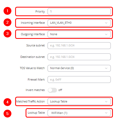
Policy Rule 1
- Enter Priority: 1
- Select Incoming interface: LAN_VLAN_ETH0
- Select Outgoing interface: None
- Select Matched Traffic Action: Lookup Table
- Lookup Table: WifiWAN(1)
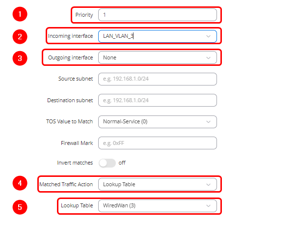
Policy Rule 2
- Enter Priority: 1
- Select Incoming interface: LAN_VLAN_3
- Select Outgoing interface: None
- Select Matched Traffic Action: Lookup Table
- Lookup Table: WiredWan(3)
Policy Rule 3
- Enter Priority: 1
- Select Incoming interface: LAN_VLAN_5
- Select Outgoing interface: None
- Select Matched Traffic Action: Lookup Table
- Lookup Table: MWan(5)
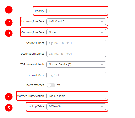
NOTE: Delete all Autimatic or unrelated routing rules
Configuration testing
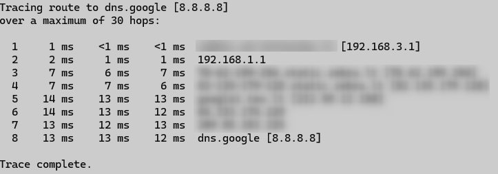
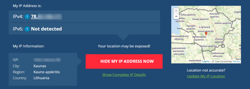
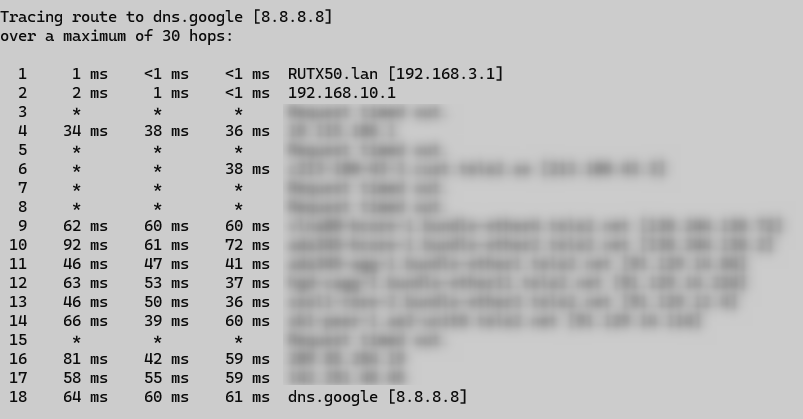
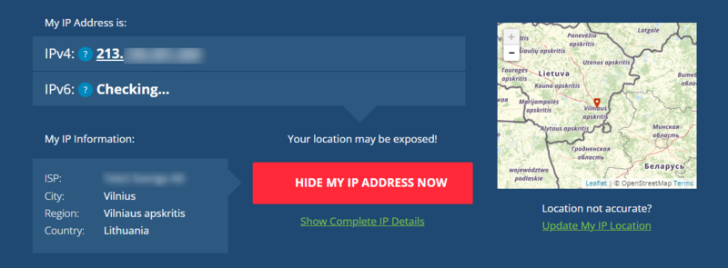
Connect end device to physical port that is assingned to different routing policy. Open cmd and run this command: tracert 8.8.8.8, three physical ports that we assigned to diffrent Vlans route to 8.8.8.8 should be using different gateways and public addresses visit to check if address changes whatismyipaddress.
Public IP addresses that are used in my topology:
- WiFi WAN: 78.xxx.xxx.xxx
- Wired WAN: 213.xxx.xxx.xxx
- Mobile WAN: 84.xxx.xxx.xxx
Physical Port 1 Test Result

Physical Port 2 Test Result
Physical Port 3 Test Result
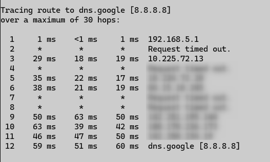
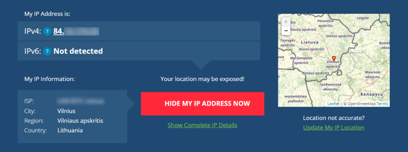
Policy Based Routing on a single Host
Single Host Routing Topology
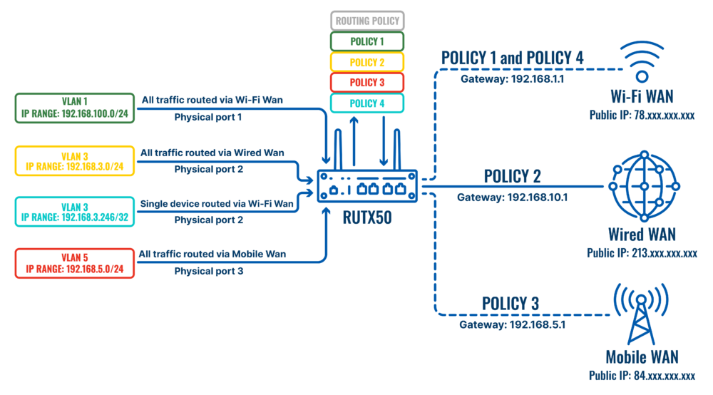
Wired WAN Routing Policy Priority Change
Open WebUI → Network → Routing → Policy based routing → Routing Rules for IPv4 and click ![]() on Policy Rule 2
on Policy Rule 2
Make following changes:
- Set Priority: 2
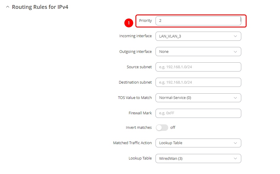
Creating New Routing Policy Rule
Open WebUI → Network → Routing → Policy based routing
Creating Single Node Routing Table Over WifiWan
Add new instance:
- Enter ID: 7
- Enter New configuration name: Node

click ![]() in the new window make following changes:
in the new window make following changes:
Static IPv4 Routes
click ![]() and apply this to the route:
and apply this to the route:
- Select Interface: WifiWan | Enter Target: 0.0.0.0 | Enter IPv4-Netmask: 0.0.0.0 | Enter IPv4-Gateway: 192.168.1.1

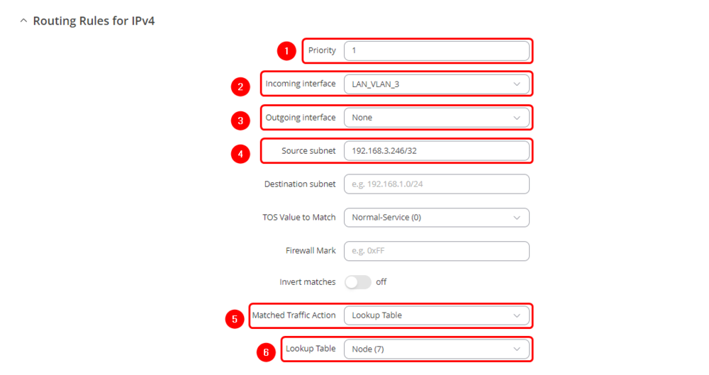
Routing Rules for IPv4
By clicking ![]() create rule under Routing Rules for IPv4 tab apply these changes to the rules:
create rule under Routing Rules for IPv4 tab apply these changes to the rules:
Policy Rule 4
- Enter Priority: 1
- Select Incoming interface: LAN_VLAN_3
- Select Outgoing interface: None
- Enter Source subnet: 192.168.3.246/32
- Select Matched Traffic Action: Lookup Table
- Lookup Table: Node (7)
Testing the Policy Route
