Difference between revisions of "RUT850 Front & Back Panels"
From Teltonika Networks Wiki
m (Protected "RUT850 Front & Back Panels" ([Edit=Allow only administrators] (indefinite) [Move=Allow only administrators] (indefinite))) |
|||
| Line 1: | Line 1: | ||
{{Template: Networking_device_manual_panels | {{Template: Networking_device_manual_panels | ||
| name = RUT850 | | name = RUT850 | ||
| − | + | | file_front = Networking_rut850_manual_panels_front_v1.png | |
| − | | file_front = | + | | file_back = Networking_rut850_manual_panels_back_v1.png |
| − | |||
| − | | file_back = | ||
| − | |||
}} | }} | ||
Revision as of 12:51, 22 June 2020
Main Page > RUT Routers > RUT850 > RUT850 Manual > RUT850 Front & Back PanelsThis page provides descriptions of the components found on the front and back panels of a RUT850 device.
Front panel

Back panel

Power socket pinout
[[File:{{{file_power}}}]]
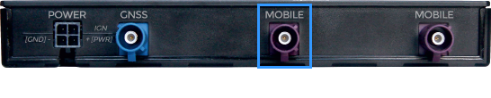
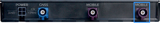
Main/Aux antenna connectors
LTE main/aux antenna connector positions depend on the product code's seventh symbol. You can find the product code on the bottom of the router, on the packaging or in the WebUI, Status → Device page.
The main/aux antenna dependency on the seventh symbol is explained in the table below:
| Seventh symbol | Main antenna | Aux antenna |
|---|---|---|
| 0, 3, 4, 5, 6, 7, 8, 9, A | Left | Right |
| 1, 2 | Right | Left |
| Left connector | Right connector |
 |
 |

