Difference between revisions of "Extending Router Hotspot Network with TAP100"
| (15 intermediate revisions by 2 users not shown) | |||
| Line 1: | Line 1: | ||
| + | |||
<p style="color:red">The information in this page is updated in accordance with [https://wiki.teltonika-networks.com/view/FW_%26_SDK_Downloads'''00.07.05.0'''] firmware version. .</p> | <p style="color:red">The information in this page is updated in accordance with [https://wiki.teltonika-networks.com/view/FW_%26_SDK_Downloads'''00.07.05.0'''] firmware version. .</p> | ||
| Line 6: | Line 7: | ||
==Configuration overview and prerequisites== | ==Configuration overview and prerequisites== | ||
| − | Before we begin, let's take a look at the configuration that we are attempting to achieve and the prerequisites that make it possible. For this setup we are going to use Teltonika router RUT956 and access point TAP100. | + | Before we begin, let's take a look at the configuration that we are attempting to achieve and the prerequisites that make it possible. For this setup we are going to use Teltonika router RUT956 which LAN IP is 192.168.5.1 and access point TAP100 which LAN IP is 192.168.5.2 |
| − | [[File: | + | [[File:Topology test test.jpg|border|class=tlt-border]] |
'''Prerequisites:''' | '''Prerequisites:''' | ||
| Line 14: | Line 15: | ||
<li> Teltonika Networks router with WiFi capabilities </li> | <li> Teltonika Networks router with WiFi capabilities </li> | ||
<li> Teltonika Networks wireless AP TAP100 connected to the LAN port of the Router </li> | <li> Teltonika Networks wireless AP TAP100 connected to the LAN port of the Router </li> | ||
| − | <li> | + | <li> Two end devices (PC, Laptop, Smartphone) </li> |
<li> RMS account (useful to have) </li> | <li> RMS account (useful to have) </li> | ||
</ul> | </ul> | ||
| Line 22: | Line 23: | ||
==Router configuration== | ==Router configuration== | ||
| − | === | + | ===Configuring router LAN interface=== |
---- | ---- | ||
| − | + | Go to '''Network -> LAN''' and press edit button and in pop-up window perform following actions : | |
<ol> | <ol> | ||
| − | <li> | + | <li>Enter IPv4 address of your choice, we are using 192.168.5.1 in this case, but you could leave the default one of 192.168.1.1 if you prefer to</li> |
| − | + | <li>Disable DHCP server </li> | |
| − | |||
| − | |||
| − | <li> | ||
</ol> | </ol> | ||
| − | [[File: | + | [[File:LAN_Hotspot.png|border|class=tlt-border]] |
| − | + | ===Router management port configuration=== | |
| − | + | Before proceeding with the configuration of the hotspot interface, it's essential to configure the management port on our router, <b>unless you choose to use RMS for the device management, then you could skip this step.<b> This is necessary because, after enabling the hotspot on the LAN interface, we will no longer be able to connect to the router using the router's LAN IP address. | |
| − | === | + | To create management port on port 1 of the device, firstly we need to navigate on router WebUI to '''Network -> VLAN -> Port based'''. While there do the following steps : |
| − | |||
<ol> | <ol> | ||
| − | <li> | + | <li>Press "ADD" button </li> |
| − | + | <li>On default VLAN ID 1 interface choose off on LAN 1 </li> | |
| − | <li> | + | <li>On newly create VLAN interface on LAN 1 port choose untagged. </li> |
| − | <li> | + | <li>Press Save & Apply </li> |
| − | |||
| − | |||
| − | |||
| − | |||
| − | |||
| − | |||
| − | <li> | ||
| − | |||
</ol> | </ol> | ||
| + | [[File:VLAN MANAGEMENT HOTSPOT.png|border|class=tlt-border]] | ||
| − | + | After this, navigate to '''Network -> LAN''' and add new interface. | |
| − | + | In pop-up window do the following steps : | |
<ol> | <ol> | ||
| − | <li>Enable | + | <li>Enable </li> |
| − | <li> | + | <li>IpV4 address : specify any private IP address. Make sure that this address will not be used for hotspot or any other instances. We are gonna choose 192.168.10.1 </li> |
| − | [[File: | + | <li>Netmask : default can be left (255.255.255.0) </li> |
| + | <li>Enable DHCP server </li> | ||
| + | [[File:VLAN MANAGEMENT HOTSPOT2.png|border|class=tlt-border]] | ||
| + | <li>In pop-up window navigate to physical settings and for interface choose eth0.3. If your newly created VLAN ID is left by default as 3, you have to choose eth0.3, but if you specify some other VLAN ID, for example VLAN 55, you will need to choose eth0.55 </li> | ||
| + | [[File:VLAN MANAGEMENT HOTSPOT3.png|border|class=tlt-border]] | ||
| − | <li> | + | <li>In pop-up window navigate to firewall settings and choose custom and enter " Management ". This will create new firewall zone. </li> |
| − | [[File: | + | [[File:VLAN MANAGEMENT HOTSPOT5.png|border|class=tlt-border]] |
| − | + | Furthermore, after creating the firewall zone on the LAN interface, please proceed to '''Network -> Firewall -> General Settings'''. It is important to ensure that the "Management" zone you created has the correct policies in place. They should be configured as follows : | |
| − | [[File: | + | <ol> |
| − | + | <li>Input : Accept </li> | |
| + | <li>Output : Accept </li> | ||
| + | <li>Forward : Accept </li> | ||
| + | <li>Cowered networks : Management </li> | ||
| + | [[File:Management port zone.png|border|class=tlt-border]] | ||
| + | </ol> | ||
</ol> | </ol> | ||
| − | + | With these configuration changes, we have made a management port on LAN 1. This allows us to access the router through the newly created interface IP (192.168.10.1), even after enabling the hotspot instance on the LAN network. | |
===Router Hotspot configuration=== | ===Router Hotspot configuration=== | ||
| Line 73: | Line 72: | ||
To set up a hotspot instance on the RUT956 router, we firstly must download the hotspot package from the device's package manager. You can access the package manager by navigating to the router's WebUI interface to '''System -> Package Manager -> Packages'''. | To set up a hotspot instance on the RUT956 router, we firstly must download the hotspot package from the device's package manager. You can access the package manager by navigating to the router's WebUI interface to '''System -> Package Manager -> Packages'''. | ||
| − | After you have successfully installed the hotspot package, the next step is to access hotspot configuration settings. | + | After you have successfully installed the hotspot package, the next step is to access hotspot configuration settings. Navigate to '''Services -> Hotspot -> Local users''' as we will be configuring local user authentication for our Hotspot instance. While in this section, please follow these steps : |
<ol> | <ol> | ||
| − | <li>Enter | + | <li>Enter username that you wish. </li> |
| − | <li>Enter | + | <li>Enter password that you wish. </li> |
| − | <li>Press add button </li> | + | <li>Press add button. </li> |
</ol> | </ol> | ||
It's crucial to remember and securely store these credentials, as they will be used by users to authenticate themselves on the hotspot network successfully. | It's crucial to remember and securely store these credentials, as they will be used by users to authenticate themselves on the hotspot network successfully. | ||
| Line 86: | Line 85: | ||
Now that we've successfully created a hotspot local user, the next step is to configure the hotspot interface. To achieve this, let's navigate to the router's WebUI and access '''Services -> Hotspot -> General'''. Once there, please follow these steps: | Now that we've successfully created a hotspot local user, the next step is to configure the hotspot interface. To achieve this, let's navigate to the router's WebUI and access '''Services -> Hotspot -> General'''. Once there, please follow these steps: | ||
<ol> | <ol> | ||
| − | <li> Choose | + | <li> Choose LAN interface.</li> |
| − | <li> Press "ADD" button </li> | + | <li> Press "ADD" button. </li> |
</ol> | </ol> | ||
| − | [[File:Hotspot | + | [[File:New Instance Hotspot.png|border|class=tlt-border]] |
Next, in the pop-up window, please click the "Enable" button. You can choose to either leave all other settings at their default values or make adjustments as per your preferences. For the purpose of this configuration, we'll maintain the default settings. | Next, in the pop-up window, please click the "Enable" button. You can choose to either leave all other settings at their default values or make adjustments as per your preferences. For the purpose of this configuration, we'll maintain the default settings. | ||
| + | |||
| + | With this configuration in place, the hotspot will be enabled on the LAN interface, allowing it to function both as a wired and wireless network simultaneously. | ||
| + | |||
| + | '''IMPORTANT :''' After enabling this hotspot interface, it's important to note that you won't be able to access the router through its IP address, unless you have previously made management port. Another way to access router without management port configurations is through our Teltonika RMS. You can find instructions on how to generate WebUI access link on RMS [https://wiki.teltonika-networks.com/view/How_to_reach_a_router%27s_WebUI_from_RMS%3F here] | ||
[[File:Hotpost interface enable.png|border|class=tlt-border]] | [[File:Hotpost interface enable.png|border|class=tlt-border]] | ||
| Line 101: | Line 104: | ||
To begin, we'll have to access TAP100's WebUI. Instructions on how to access the TAP100 WebUI can be found in another article on our Wiki [https://wiki.teltonika-networks.com/view/QSG_TAP100#Login_to_device here] | To begin, we'll have to access TAP100's WebUI. Instructions on how to access the TAP100 WebUI can be found in another article on our Wiki [https://wiki.teltonika-networks.com/view/QSG_TAP100#Login_to_device here] | ||
| − | After successfully establishing a connection to the TAP100 WebUI, the next step is to navigate to '''Network -> | + | After successfully establishing a connection to the TAP100 WebUI, the next step is to navigate to '''Network -> IP settings'''. Within this section, update the IPv4 address field to match the LAN network of your router. For instance, if your router's LAN belongs to the network 192.168.5.0/24 with a LAN IP address of 192.168.5.1, then configure your TAP100 with an IP address of 192.168.5.2 and a netmask of 255.255.255.0. This ensures that both devices are on the same network. |
| − | |||
| − | + | [[File:TAP100 IP address.png|border|class=tlt-border]] | |
| − | [[File: | ||
| − | That concludes the necessary configuration steps for the TAP100. Now, let's establish the connection between your router and the TAP100. To do this, you can simply connect one end of an Ethernet cable to the router's | + | That concludes the necessary configuration steps for the TAP100. Now, let's establish the connection between your router and the TAP100. To do this, you can simply connect one end of an Ethernet cable to the router's LAN port and the other end to the TAP100's Ethernet IN port on the PoE injector. For more detailed installation instructions, please refer to the installation guide which can be found [https://wiki.teltonika-networks.com/view/QSG_TAP100#Installation_Guide here] |
| − | + | ||
| − | + | ==Access router through hotspot== | |
| − | With the current configuration, clients | + | With the current configuration, clients have access to the TAP100 WebUI but cannot reach the router's WebUI. This section outlines additional steps to enable hotspot clients to access the router's WebUI. |
To achieve this, we only need to create one firewall rule on the router. Here's how to do it: | To achieve this, we only need to create one firewall rule on the router. Here's how to do it: | ||
| Line 125: | Line 126: | ||
<li> Press "ADD" button </li> | <li> Press "ADD" button </li> | ||
</ol> | </ol> | ||
| − | [[File: | + | [[File:firewallrule1.png|border|class=tlt-border]] |
After completing these steps, a pop-up window will appear, where you need to enter the following details: | After completing these steps, a pop-up window will appear, where you need to enter the following details: | ||
| Line 136: | Line 137: | ||
</ol> | </ol> | ||
[[File:Firewallrule2.png|border|class=tlt-border]] | [[File:Firewallrule2.png|border|class=tlt-border]] | ||
| − | With this firewall rule in place, all clients connected to the hotspot will have access to the router's WebUI using the router LAN address. | + | With this firewall rule in place, all clients connected to the hotspot will have access to the router's WebUI using the router LAN address (in our case, 192.168.5.1) and can reach the TAP100 WebUI via the tap100.rutos.net address. |
| + | ==Disabling wired hotspot capabilities on the router== | ||
| + | With the initial setup, our router is capable of providing both a wired and wireless hotspot network. If you wish to disable the wired hotspot capabilities on the router, you can do so by accessing the router's WebUI and navigating to '''Network -> VLAN -> Port Based'''. In this section, simply select the "OFF" option for the ports you want to disable. It's important to keep in mind that you cannot disable all LAN ports since one of them is necessary for connecting to the TAP100. | ||
| + | For example, if you have configured the management port on LAN 1 port, your TAP100 is connected to LAN 3 port, and you want to disable the wired hotspot capabilities on LAN 2, your VLAN configuration page should look like this : | ||
| + | [[File:Disabled wired hotspot.png|border|class=tlt-border]] | ||
| + | |||
| − | + | ==Isolating hotspot clients communication== | |
| − | In our default setup, hotspot clients have the ability to communicate with each other. To restrict this communication, we'll need to make an adjustment on both | + | In our default setup, hotspot clients have the ability to communicate with each other. To restrict this communication, we'll need to make an adjustment on both your TAP100 device and your router. |
<ol> | <ol> | ||
| − | <li> Access your TAP100 WebUI </li> | + | <li> Access your TAP100 WebUI. </li> |
| − | <li> Navigate to '''Network -> Wireless''' and click on the "Edit" button for your interface </li> | + | <li> Navigate to '''Network -> Wireless''' and click on the "Edit" button for your interface. </li> |
| − | <li> In the configuration window, go to the Advanced Settings section and enable the "Isolate Clients" option by clicking the "ON" button </li> | + | <li> In the configuration window, go to the Advanced Settings section and enable the "Isolate Clients" option by clicking the "ON" button. </li> |
</ol> | </ol> | ||
[[File:ISOLATE CLIENTS HOTSPOT.png|border|class=tlt-border]] | [[File:ISOLATE CLIENTS HOTSPOT.png|border|class=tlt-border]] | ||
| Line 156: | Line 162: | ||
After entering the required details, clients will have internet connection. The credentials you need to use are the ones you specified when creating the local user earlier. | After entering the required details, clients will have internet connection. The credentials you need to use are the ones you specified when creating the local user earlier. | ||
| − | === | + | ===Client to client testing=== |
| − | + | As mentioned in this article before, clients connected to hotspot network can communicate with each other unless "Isolate Clients" option is turned on. | |
| − | |||
Revision as of 14:15, 24 October 2023
The information in this page is updated in accordance with 00.07.05.0 firmware version. .
Introduction
This article provides instructions on how to expand the hotspot network of the RUT956 router using the TAP100 access point. It's important to clarify that TAP100 cannot function as an independent hotspot network - it serves as an access point. The network management and control will be handled by the RUT device, with the TAP100 extending the coverage area.
Configuration overview and prerequisites
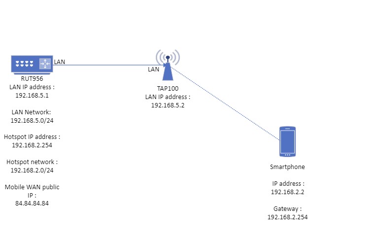
Before we begin, let's take a look at the configuration that we are attempting to achieve and the prerequisites that make it possible. For this setup we are going to use Teltonika router RUT956 which LAN IP is 192.168.5.1 and access point TAP100 which LAN IP is 192.168.5.2
Prerequisites:
- Teltonika Networks router with WiFi capabilities
- Teltonika Networks wireless AP TAP100 connected to the LAN port of the Router
- Two end devices (PC, Laptop, Smartphone)
- RMS account (useful to have)
If you're having trouble finding any page or some of the parameters described here on your device's WebUI, you should turn on "Advanced WebUI" mode. You can do that by clicking the "Advanced" button, which is located at the top-right corner of the WebUI.

Router configuration
Configuring router LAN interface
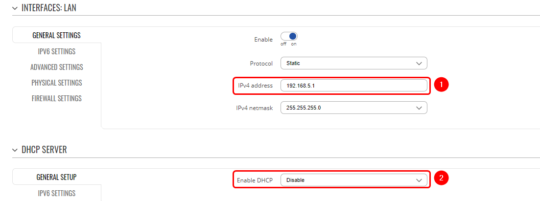
Go to Network -> LAN and press edit button and in pop-up window perform following actions :
- Enter IPv4 address of your choice, we are using 192.168.5.1 in this case, but you could leave the default one of 192.168.1.1 if you prefer to
- Disable DHCP server
Router management port configuration
Before proceeding with the configuration of the hotspot interface, it's essential to configure the management port on our router, unless you choose to use RMS for the device management, then you could skip this step. This is necessary because, after enabling the hotspot on the LAN interface, we will no longer be able to connect to the router using the router's LAN IP address. To create management port on port 1 of the device, firstly we need to navigate on router WebUI to Network -> VLAN -> Port based. While there do the following steps :
- Press "ADD" button
- On default VLAN ID 1 interface choose off on LAN 1
- On newly create VLAN interface on LAN 1 port choose untagged.
- Press Save & Apply
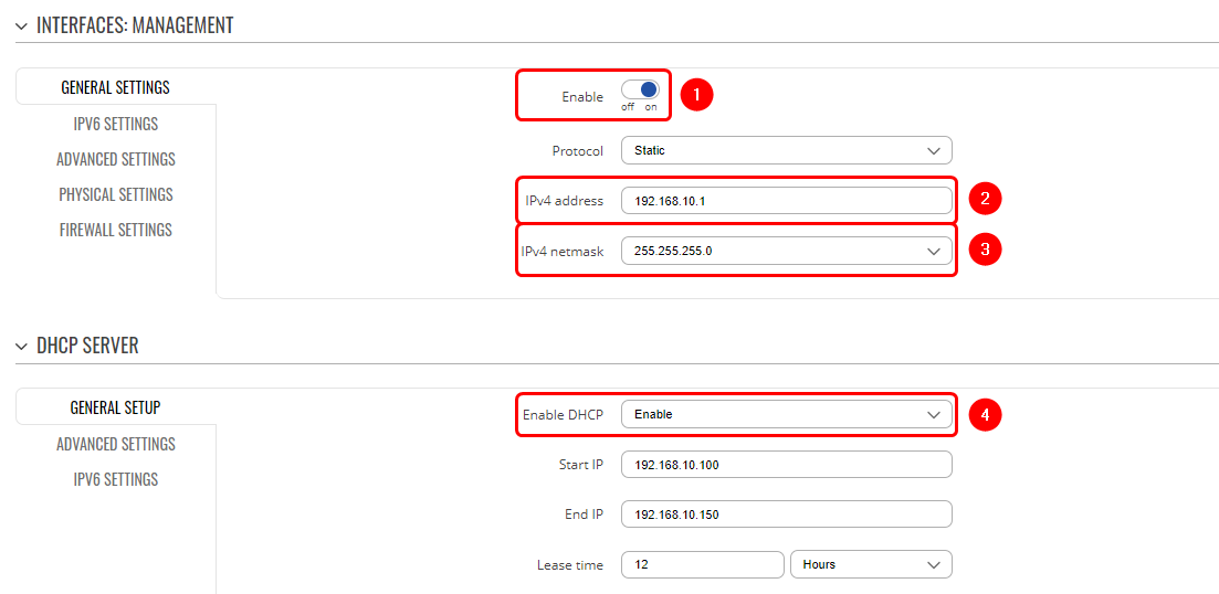
After this, navigate to Network -> LAN and add new interface. In pop-up window do the following steps :
- Enable
- IpV4 address : specify any private IP address. Make sure that this address will not be used for hotspot or any other instances. We are gonna choose 192.168.10.1
- Netmask : default can be left (255.255.255.0)
- Enable DHCP server
- In pop-up window navigate to physical settings and for interface choose eth0.3. If your newly created VLAN ID is left by default as 3, you have to choose eth0.3, but if you specify some other VLAN ID, for example VLAN 55, you will need to choose eth0.55
- In pop-up window navigate to firewall settings and choose custom and enter " Management ". This will create new firewall zone.

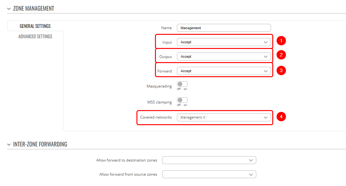
 Furthermore, after creating the firewall zone on the LAN interface, please proceed to Network -> Firewall -> General Settings. It is important to ensure that the "Management" zone you created has the correct policies in place. They should be configured as follows :
With these configuration changes, we have made a management port on LAN 1. This allows us to access the router through the newly created interface IP (192.168.10.1), even after enabling the hotspot instance on the LAN network.
Router Hotspot configuration
Creating hotspot local user
To set up a hotspot instance on the RUT956 router, we firstly must download the hotspot package from the device's package manager. You can access the package manager by navigating to the router's WebUI interface to System -> Package Manager -> Packages.
After you have successfully installed the hotspot package, the next step is to access hotspot configuration settings. Navigate to Services -> Hotspot -> Local users as we will be configuring local user authentication for our Hotspot instance. While in this section, please follow these steps :
- Enter username that you wish.
- Enter password that you wish.
- Press add button.
It's crucial to remember and securely store these credentials, as they will be used by users to authenticate themselves on the hotspot network successfully.

Hotspot interface configuration
Now that we've successfully created a hotspot local user, the next step is to configure the hotspot interface. To achieve this, let's navigate to the router's WebUI and access Services -> Hotspot -> General. Once there, please follow these steps:
- Choose LAN interface.
- Press "ADD" button.
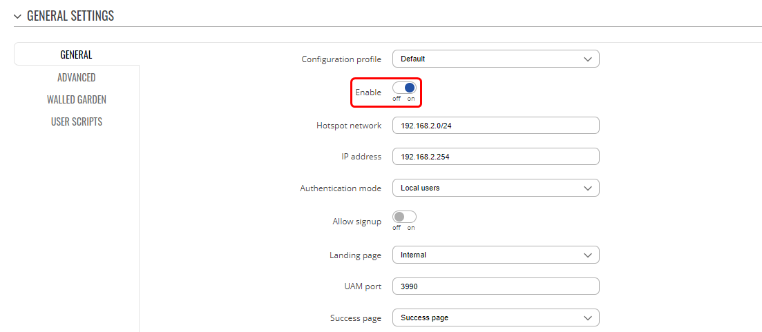
Next, in the pop-up window, please click the "Enable" button. You can choose to either leave all other settings at their default values or make adjustments as per your preferences. For the purpose of this configuration, we'll maintain the default settings.
With this configuration in place, the hotspot will be enabled on the LAN interface, allowing it to function both as a wired and wireless network simultaneously.
IMPORTANT : After enabling this hotspot interface, it's important to note that you won't be able to access the router through its IP address, unless you have previously made management port. Another way to access router without management port configurations is through our Teltonika RMS. You can find instructions on how to generate WebUI access link on RMS here
Access point (TAP100) configuration
From the router's perspective, we've successfully configured all the necessary settings. Now, let's proceed to configure the TAP100.
To begin, we'll have to access TAP100's WebUI. Instructions on how to access the TAP100 WebUI can be found in another article on our Wiki here
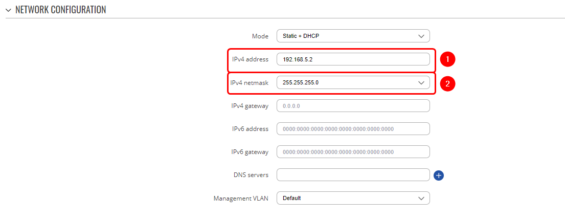
After successfully establishing a connection to the TAP100 WebUI, the next step is to navigate to Network -> IP settings. Within this section, update the IPv4 address field to match the LAN network of your router. For instance, if your router's LAN belongs to the network 192.168.5.0/24 with a LAN IP address of 192.168.5.1, then configure your TAP100 with an IP address of 192.168.5.2 and a netmask of 255.255.255.0. This ensures that both devices are on the same network.
That concludes the necessary configuration steps for the TAP100. Now, let's establish the connection between your router and the TAP100. To do this, you can simply connect one end of an Ethernet cable to the router's LAN port and the other end to the TAP100's Ethernet IN port on the PoE injector. For more detailed installation instructions, please refer to the installation guide which can be found here
Access router through hotspot
With the current configuration, clients have access to the TAP100 WebUI but cannot reach the router's WebUI. This section outlines additional steps to enable hotspot clients to access the router's WebUI.
To achieve this, we only need to create one firewall rule on the router. Here's how to do it:
To do this, navigate on router WebUI to Network -> Firewall -> Traffic Rules.
Once there, we need to create new rule with the following details :
- Type : Add new forward rule
- Name : Enter any desired name for this rule
- Source Zone : hotspot
- Destination Zone : lan (we will modify this later)
- Press "ADD" button
After completing these steps, a pop-up window will appear, where you need to enter the following details:
- Protocol: TCP
- Destination Zone : Device (input)
- Destination Port : HTTP (80), HTTPS(443)
- Don't forget to enable and save it
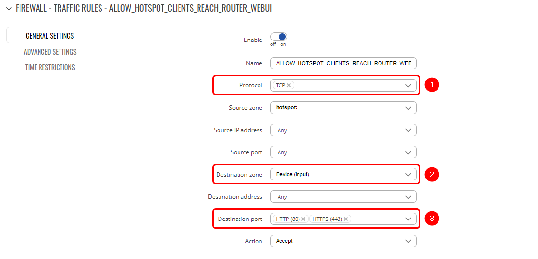 With this firewall rule in place, all clients connected to the hotspot will have access to the router's WebUI using the router LAN address (in our case, 192.168.5.1) and can reach the TAP100 WebUI via the tap100.rutos.net address.
Disabling wired hotspot capabilities on the router
With the initial setup, our router is capable of providing both a wired and wireless hotspot network. If you wish to disable the wired hotspot capabilities on the router, you can do so by accessing the router's WebUI and navigating to Network -> VLAN -> Port Based. In this section, simply select the "OFF" option for the ports you want to disable. It's important to keep in mind that you cannot disable all LAN ports since one of them is necessary for connecting to the TAP100.
For example, if you have configured the management port on LAN 1 port, your TAP100 is connected to LAN 3 port, and you want to disable the wired hotspot capabilities on LAN 2, your VLAN configuration page should look like this :

Isolating hotspot clients communication
In our default setup, hotspot clients have the ability to communicate with each other. To restrict this communication, we'll need to make an adjustment on both your TAP100 device and your router.
- Access your TAP100 WebUI.
- Navigate to Network -> Wireless and click on the "Edit" button for your interface.
- In the configuration window, go to the Advanced Settings section and enable the "Isolate Clients" option by clicking the "ON" button.
 To further ensure that clients connected to the router's Wi-Fi interface cannot communicate with hotspot clients, I recommend enabling the "Isolate Clients" option on your router wi-fi interface as well.
By implementing these adjustments, you'll effectively prevent communication between all hotspot clients regardless of whether they are connected to the Routers Hotspot Network directly or through TAP 100 AP.
Testing
Authenticating to the Hotspot network
After client connects to hotspot network, the authentication page should automatically open up on your default browser.
 After entering the required details, clients will have internet connection. The credentials you need to use are the ones you specified when creating the local user earlier.
Client to client testing
As mentioned in this article before, clients connected to hotspot network can communicate with each other unless "Isolate Clients" option is turned on.
