RUT955 USB Tools (legacy WebUI)
The information in this page is updated in accordance with firmware version RUT9XX_R_00.06.09.5.
Note: this user manual page is for RUT955's old WebUI style available in earlier FW versions. Click here for information based on the latest FW version.
Summary
The USB Tools page is used to manage services related to the device's USB connector.
This chapter of the user manual provides an overview of the USB Tools page in RUT955 devices.
USB Tools is additional software that can be installed from the System → Package Manager page.
The Network Shares section is used to manage Network-attached storage (NAS) such as USB drives, SD cards and hard drives. The router supports the following file system architectures:
- FAT32*
- NTFS**
* supports SD cards with a capacity of up to 32 GB
** NTFS support available from FW version RUT9XX_R_00.05.02 and newer
Mounted File Systems
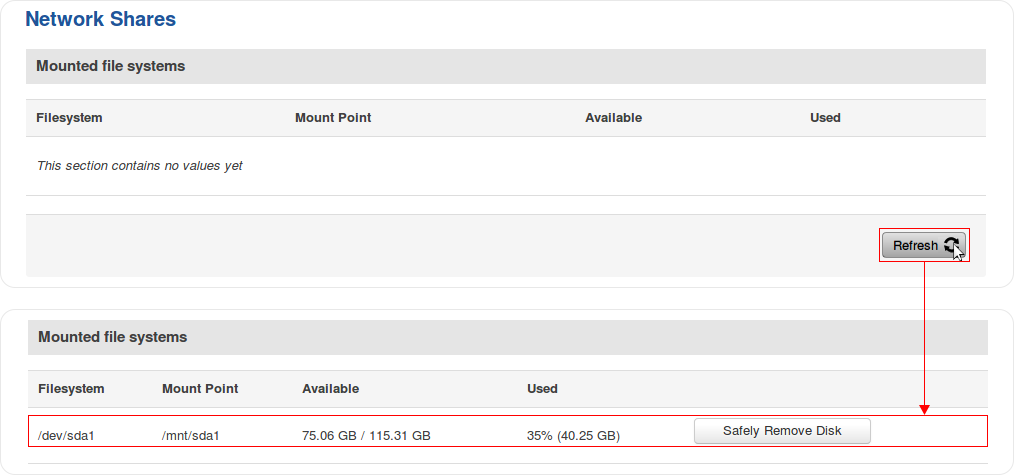
The Mounted File Systems tab displays information on mounted USB drives and SD cards. To view an attached drive, connect it to the router and click the Refresh button:
| field name | description |
|---|---|
| Filesystem | Name of the Linux filesystem. For better clarity, lets take a closer look at the filesystem name from the example above:
* SD cards will be identified as MultiMediaCard (MMC) devices and the identifier will begin with the mmcblk string instead of sd |
| Mount Point | A mount point is a directory in the currently accessible filesystem on which an additional filesystem is mounted (i.e., logically attached). The /mnt directory and its subdirectories are intended for use as the temporary mount points for mounting storage devices. The mount point becomes the root directory of the newly added filesystem, and that filesystem becomes accessible from that directory |
| Available | Amount of available memory in the mounted drive. This column also displays the total capacity of the drive |
| Used | Amount of used memory in the mounted drive |
| Safely Remove Disk | Unmounts the drive so that it becomes safe to disconnect from the router |
SSH commands
Devices can be mounted or unmounted manually by using SSH commands.
Mounting
The mount command attaches a filesystem to the file hierarchy. The basic syntax for the command is:
mount -t type device dir
Where:
- -t - the filesystem type. If this value is omitted, the command will try to determine the type automatically
- device - file name of the device. Refer to section 2.1 for examples
- dir - directory that will be used as the mount point for the device. Refer to section 2.1 for examples
Example command:
mount -t ntfs /dev/sda1 /mnt/sda1
Unmounting
The umount command detaches filesystem from the file hierarchy. The basic syntax for the command is:
umount device
Example command:
umount /dev/sda1
Using the umount command is analogous to clicking the "Safely Remove Disk" button. Therefore, the attached drive can be safely disconnected after using umount to detach it.
Samba
Samba is a software solution for using the Server Message Block (SMB) networking protocol, which provides shared file access between nodes on a computer network. The Samba tab in RUT955's WebUI is used to configure network access (look to section 2.2.1 for details) to storage devices connected to the router's MicroSD slot or USB connector.
| Field | Value | Description |
|---|---|---|
| Enable | yes | no; default: no | Turns Samba on or off. |
| Hostname | string; default: Router_share | Name of the Samba server. |
| Description | string; default: Router_share | Short description about the Same server. |
| Workgroup | string; default: WORKGROUP | Name of the server's workgroup. |
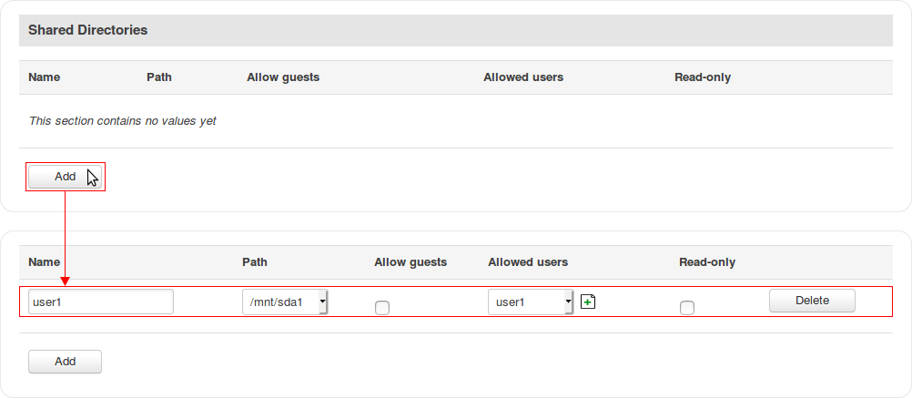
The Shared Directories section is used to configure access to connected storage drives or individual directories contained in those drives. A shared directory must be added before it can be configured:
| Field | Value | Description |
|---|---|---|
| Name | string; default: none | Name of a shared directory. |
| Path | filepath; default: /mnt/ | Path to a shared directory. To share an entire drive, choose an automatically generated path from this drop-down box (for example, /mnt/sda1). To share a specific directory on the drive, specify the full path to that directory (for example, /mnt/sda1/shared/video). |
| Allow guests | yes | no; default: no | Turns guest access on or off. Guest access allows anonymous connections to a Shared Directory. |
| Allowed users | samba user(s); default: none | Samba user(s) that are permitted to access a Shared Directory. Users can be created from the Samba Users section. |
| Read-only | yes | no; default: no | Makes a Shared Directory read-only, which means the directory can only be accessed to view and read files (not write). |
| Delete | -(interactive button) | Deletes a Shared Directory configuration. |
Samba Users
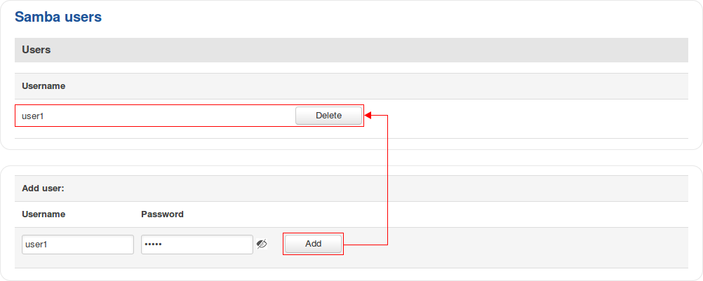
Samba users are users that can be granted access to shared directories (as described in section 2.2.1. To add a new user, enter a custom username and password and click the 'Add' button:
| Field | Value | Description |
|---|---|---|
| Username | string; default: none | Custom name for a new Samba user. |
| Password | string; default: none | Password for a new Samba user. |
Printer Server
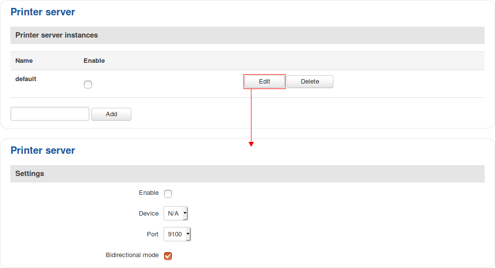
The Printer Server provides the possibility to configure access to a printer that is connected to the USB port of the RUT955 device. The Add button lets you add and manage additional printers. To configure a printer instance, click the Edit button located next to it:
| Field | Value | Description |
|---|---|---|
| Enable | yes | no; default: no | Turns USB printer support on or off. |
| Device | filepath; default: /dev/usb/lp0 | Printer's device file. |
| Port | integer [9100..9109]; default: 9100 | Printer's TCP port. |
| Bidirectional mode | off | on; default: on | Turns bidirectional mode on or off. |
For step-by-step instructions on how to use a printer with RUT955, click here
USB to Serial
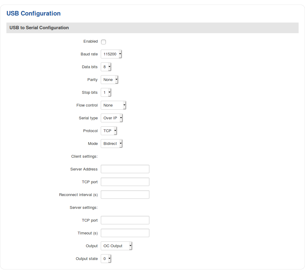
The router's USB connector can also be used as a serial port. The only type of serial connection available via USB is Over IP.
In Over IP serial type the device provides a connection to a TCP/IP network for the devices connected via the serial interface. The figure below is an example of available configuration fields for the Over IP serial type and the table below provides information on these fields:
| Field | Value | Description |
|---|---|---|
| Enabled | yes | no; default: no | Turns the USB to Serial service on or off. |
| Baud rate | 300 | 1200 | 2400 | 4800 | 9600 | 19200 | 38400 | 57600 | 115200; default: 115200 | Data rate for serial data transmission (in bits per second). |
| Data bits | 5 | 6 | 7 | 8; default: 8 | Number of data bits for each character |
| Parity | None | Odd | Even; default: None | In serial transmission, parity is a method of detecting errors. An extra data bit is sent with each data character, arranged so that the number of 1 bits in each character, including the parity bit, is always odd or always even. If a byte is received with the wrong number of 1s, then it must have been corrupted. However, an even number of errors can pass the parity check.
|
| Stop bits | 1 | 2; default: 1 | Stop bits sent at the end of every character allow the receiving signal hardware to detect the end of a character and to resynchronise with the character stream. Electronic devices usually use one stop bit. Two stop bits are required if slow electromechanical devices are used. |
| Flow control | None | RTS/CTS | Xon/Xoff; default: None | In many circumstances a transmitter might be able to send data faster than the receiver is able to process it. To cope with this, serial lines often incorporate a "handshaking" method, usually distinguished between hardware and software handshaking.
|
| Serial type | Over IP; default: Over IP | Specifies the serial connection type. |
| Protocol | TCP; default: TCP | Protocol used in the communication process |
| Mode | Server | Client | Bidirect; default: Server | The role of this device in the serial connection:
|
| No leading zeros | yes | no; default: no | When checked, indicates that the first hex zeros should be skipped |
| Client settings: Server address | ip | host; default: none | IP address or hostname of the server that the client will connect to |
| Client settings: TCP port | integer [0..65535]; default: none | Server's port number |
| Client settings: Reconnect interval (s) | integer; default: none | Time period (in seconds) between reconnection attempts in case a connection fails |
| Server settings: TCP port | integer [0..65535]; default: none | Internal TCP port number used to listen for incoming connections |
| Server settings: Timeout (s) | integer; default: none | Disconnects clients after they remain inactive for an amount time (in seconds) specified in this field |
| Output | OC Output | Relay Output; default: OC Output | Output to indicate that the application switched from client (default) to server state (this field becomes visible only in Bidirect mode) |
| Output state | 1 | 0; default: 0 | Output state value during which the application reverts to server mode (this field becomes visible only in Bidirect mode) |
USB Modem
Click here for step-by-step USB modem set up instructions.
RUT955 devices are compatible with the following USB modems:
- Huawei MS2131i-8
