DLMS client configuration example
The information in this page is updated in accordance with 00.07.05.4 firmware version.
Introduction
DLMS (Device Language Message Specification) is a set of standards used for communication between various meters, monitoring equipment, and the respective controllers. It uses TCP/IP or serial communication and utilizes Client and Server topology, where the client polls the data from the server (usually gas/electricity/water meter). It should be noted, that there often is confusion between IEC 62056-21 and DLMS. IEC 62056-21 is not DLMS and is not currently supported by our devices.
COSEM (Companion Specification for Energy Metering) is a protocol that falls under the DLMS standard. It provides application and transport layers for the protocol. COSEM defines a set of objects that represent the data and functions of the meter, and a set of services that allow the client to access the objects. COSEM also specifies the security mechanisms for authentication and encryption of the messages. It should be noted, that for now our implementation of COSEM only allows us to perform read operations on DLMS meters, with write operations not currently being supported.
What problems can our DLMS implementation solve?
Let's say your company is responsible for monitoring the electricity and gas consumption of a factory. Instead of having separate equipment for monitoring both meters, sending the data to a remote server, and providing internet connectivity, RUT956 can do it all in one single compact package:
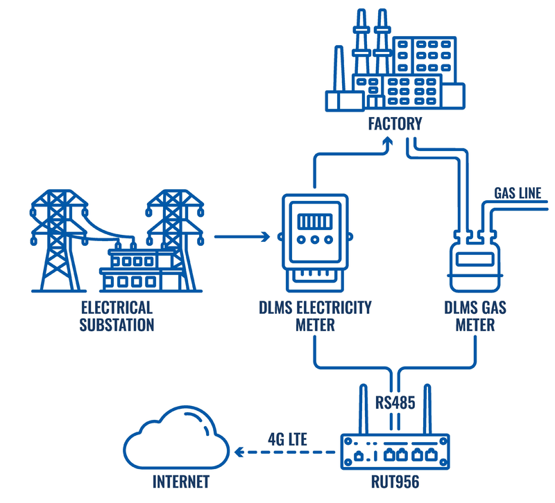
In an event of connection loss, RUT956 can store the DLMS data in the volatile memory, and send it to the monitoring platform once the connectivity is restored. This way you will ensure data integrity and accurate monitoring results.
Various VPN services on our devices can keep data secure along its way to your monitoring servers, as well as ensuring RUT956 and the connected devices reachability remotely.
Configuration
The first step in getting DLMS up and running will be to configure the connection to a device. Here we will cover both TCP/IP and serial connection configuration. To get started with DLMS, a separate DLMS Client package needs to be downloaded from our package manager, which can be found by navigating to System → Package Manager → Packages.
Connection configuration
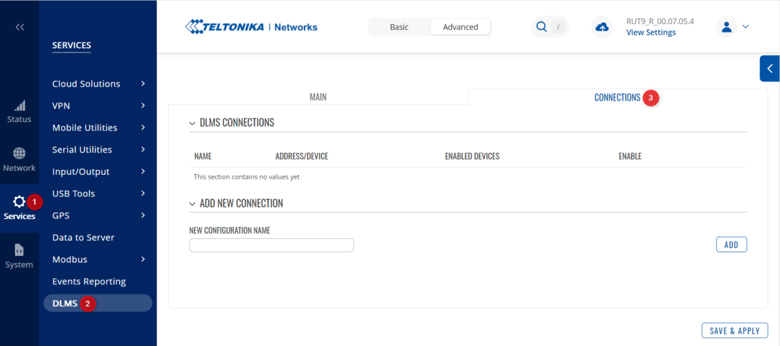
Once installed, we can head over to Services → DLMS. Select the Connections tab:
TCP/IP
- Create a new instance with an easily recognizable name and press the Add button;
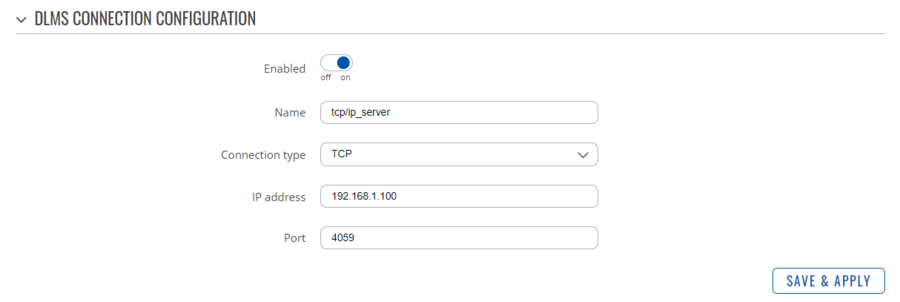
- When the configuration window opens up, specify:
- Connection type as TCP;
- IP address of the DLMS meter. It can be assigned statically or dynamically using DHCP;
- Port number of the DLMS access. Usually, the port used for DLMS/COSEM is anywhere from 4059 to 4063. Please refer to a manual of your device to check which port is used by your device;
After the connection parameters are entered, do not forget to enable the instance! The configuration could look similar to this:
Serial
- Create a new instance with an easily recognizable name and press the Add button;
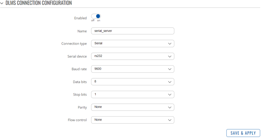
- When the configuration window opens up, specify:
- Connection type as Serial;
- Under the Serial device field, specify whether you're using RS485 or RS232;
- Specify the remaining serial parameters. They can either be configured in the DLMS meter itself, or the default ones should be specified within the user manual;
The final configuration could look like so:
Physical device configuration
Once we have configured the basic connection parameters, we can move onto configuring the physical DLMS devices. Back in the Main tab, we can create a new DLMS physical device interface with a recognizable name. Once the instance is created, and the configuration window opens up, there are a few parameters we need to specify:
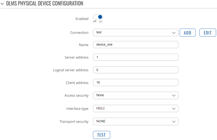
- Select the connection instance created earlier;
- HDLC Addressing
- Specify the Server address. This address is also commonly known as Physical device address or Lower address. For a single physical device, there can only be one physical server address! This parameter is mainly used in serial connections where there are no other means of addressing a device.
- Specify the Logical server address. It is also commonly known as the Upper address. A single physical device can have more than one logical address. Each logical server can have their own client addresses, access security levels, etc.
- Client addressing
- Client address, as defined by the standard, relates to the permissions of the user. Each client address represents a different Access security level:
- Client address 16 - None;
- Client address 17 - Low;
- Client address 18 - High;
- The client address should be specified in the user manual of the DLMS meter. However, if you are not able to find this information, the most commonly used address is 16 with no authentication. Keep in mind, that some manufacturers may not follow the standard and use Client addresses that do not follow the scheme mentioned above.
- Client address, as defined by the standard, relates to the permissions of the user. Each client address represents a different Access security level:
- Interface type
- We currently support two DLMS interface types:
- Wrapper - can only be used with TCP/IP connections, but is simpler to implement;
- HDLC - can be used with both serial and TCP/IP connections. We currently support direct serial connections, as well as IEC 62056-21 protocol mode E / HDLC with mode E interfaces, which contain an optical probe on one end, and RS interface on the other.
- We currently support two DLMS interface types:
- Transport security
- Transport security, unlike access security, specifies on how the data should be encrypted when being transferred via the TCP/IP or Serial communication lines. This parameter can also be found in the user manual of the DLMS meter. It has 4 possible levels of security.
Testing physical device reachability
Finally, once we have configured the physical DLMS device, we can test if our configuration up until this point was correct by enabling the DLMS Client package, the created physical device instance, saving the settings, and pressing the TEST button:
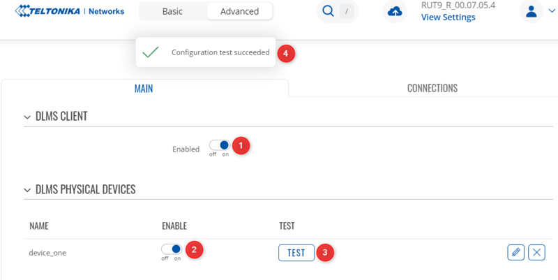
If you're receiving an error, open physical device instance, and press the TEST button at the bottom. It will provide a more specific error message:

DLMS group configuration
Now that the physical devices are configured and working, let's move onto COSEM group configuration. COSEM groups are a convenient way to organize the OBIS codes that you want to send to the remote data collection server. You can add OIDs from different physical devices to the same COSEM group.
The first thing to do is to choose how frequently you want to read the data from the devices. For TCP/IP devices, one second is a good interval. For serial devices, you may need to use a longer interval, depending on the baud rate. This is to avoid reading the data too fast and causing errors.

COSEM value configuration
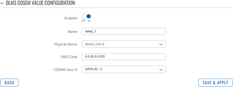
Each COSEM value needs to be created for every OBIS code that needs to be read from the DLMS meter. In this window we will need to specify:
- Physical device that we will be reading the value from;
- OBIS code of the value that we would like to read;
- OBIS codes specify the location of the data on the DLMS meter, and they can be found in the user manual of your device.
- It should be in the following format: A.B.C.D.E.F (for example, 1.0.1.4.6.255). OBIS codes are comprised of 6 groups, and each group represents a different piece of information about the OID in question. More information about it can be found in the sources linked at the end of the article.
- The same OBIS code can be read from multiple devices/logical devices at the same time;
- COSEM class ID (also known as COSEM object) specifies the format in which the data will be returned. The most commonly used ones are DATA (ID: 1) and REGISTER (ID: 3), however, this information should be available in the user manual of your DLMS meter along with each OBIS code.
Here is an example of a configured COSEM value:
Testing the configuration
Once all of the configuration is enabled and saved, we can re-open the COSEM group we have created, and press the TEST button. If the configuration is correct, we should see the information returned in JSON format, as well as a green checkmark next to each COSEM value:
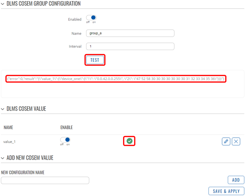
If the service fails to obtain one or more COSEM values, you'll get an error within the JSON string, as well as when hovering over the exclamation mark next to each COSEM value in question:
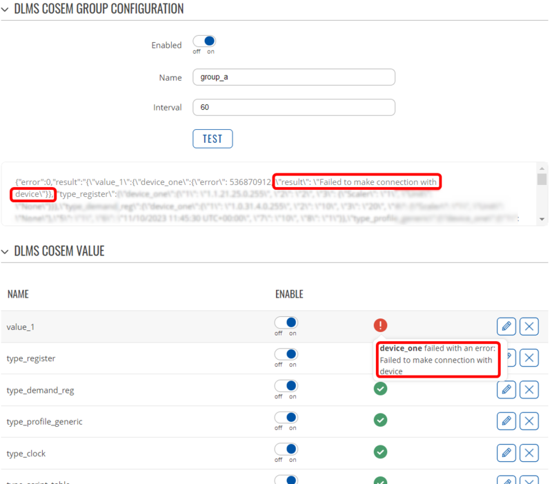
The JSON string will then be available in the Data to Server service, which then can send the data to your remote data collection server. Values can be filtered in the Data to server module by their COSEM group names.
References
- DLMS in a nutshell by GuruX: https://www.gurux.fi/DLMSInNutshell
- COSEM Class IDs: https://www.gurux.fi/Gurux.DLMS.Objects
- DLMS FAQ: https://www.gurux.fi/DLMSCOSEMFAQ
