DMVPN (Phase 3) with OSPF configuration example
The information on this page is updated in accordance with the 00.07.07.2 firmware version .
Introduction
DMVPN stands for Dynamic Multipoint VPN. It's a specific type of VPN technology designed for efficiently connecting multiple remote sites (like branch offices) to a central headquarters over the internet. Unlike traditional point-to-point VPNs that require separate tunnels for each branch office to connect to the central hub, DMVPN uses a hub-and-spoke model. Spoke locations (branch offices) can directly communicate with each other and the central hub securely, without needing all traffic to flow through the central hub.
If You have trouble seeing any of the settings, be sure to enable "Advanced mode"

Topology
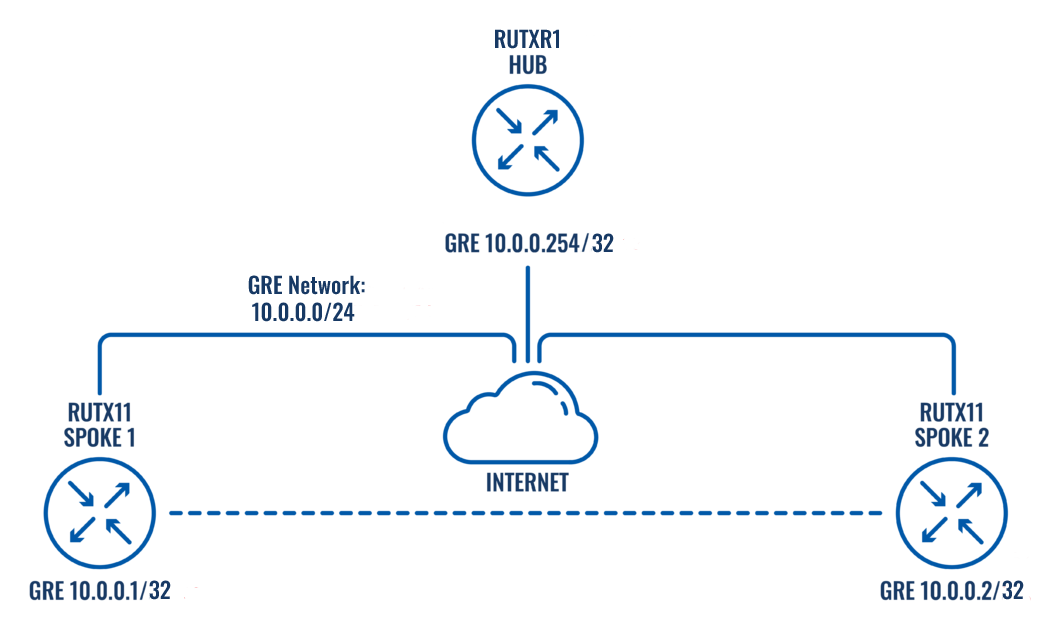
- DMVPN HUB - GRE interface address - 10.0.0.254 - LAN interface address 192.168.254.1
- DMVPN SPOKE1 - GRE interface address - 10.0.0.1 - LAN interface address 192.168.1.1
- DMVPN SPOKE2 - GRE interface address - 10.0.0.2 - LAN interface address 192.168.2.1
Creating DMVPN network
HUB's configuration
Navigate to Services → VPN → DMVPN
Create a new instance with a name of Your choice. In this example, we will name it "HUB"

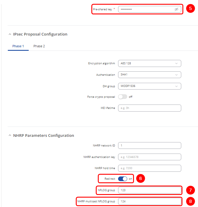
Configure the HUB as shown:
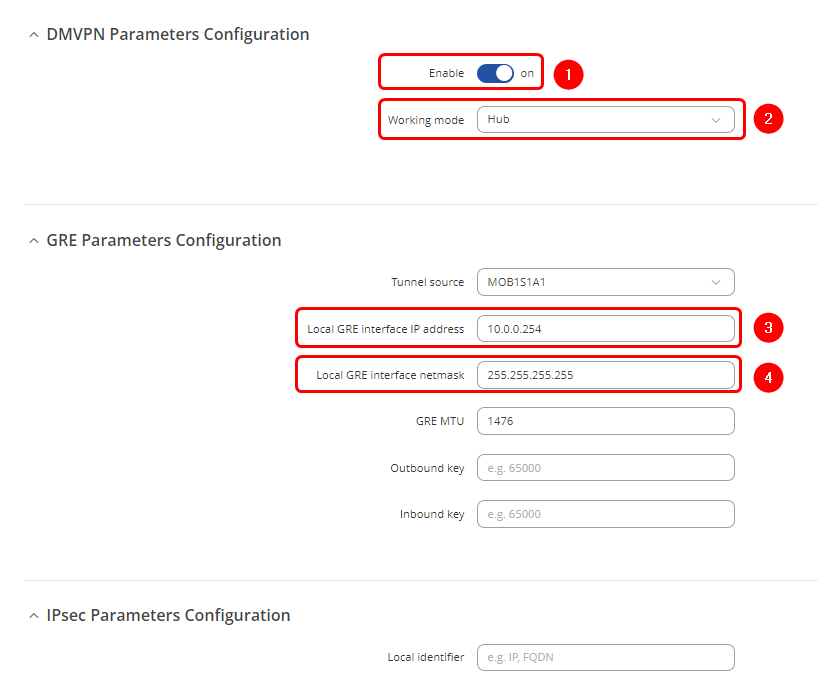
- 1. Enable - On
- 2. Working mode - Hub
- 3. Local GRE interface IP address - 10.0.0.254
- 4. Local GRE interface netmask - 255.255.255.255
- 5. Pre-shared key - Create a password which will be used in authentication
- 6. Redirect - On
- 7. NFLOG group - 123
- 8. NHRP multicast NFLOG group - 124 (different than NFLOG group number)
SPOKE's configuration
Navigate to Services → VPN → DMVPN
Create a new instance with a name of Your choice. In this example, we will name it "SPOKE1"
Configure the SPOKE1 as shown:
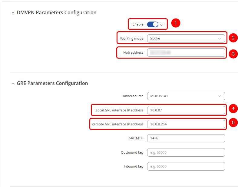
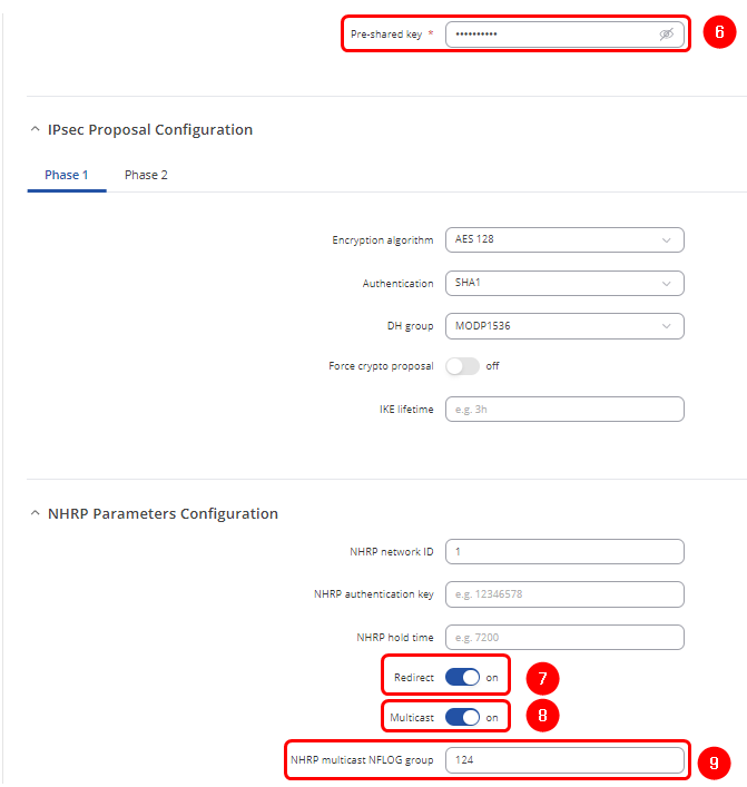
- 1. Enable - On
- 2. Working mode - Spoke
- 3. Hub address - Public IP address of the Hub
- 4. Local GRE interface IP address - 10.0.0.1
- 5. Remote GRE interface IP address - 10.0.0.254
- 6. Pre-shared key - Use the same password that was created in the Hub's configuration
- 7. Redirect - On
- 8. Multicast - On
- 9. NHRP multicast NFLOG group - 124 (same number that was in the Hub's configuration)
Configuration for the SPOKE2 will be analog to SPOKE1, with the exception of name being SPOKE2 and Local GRE interface IP address being 10.0.0.2
Testing DMVPN's connectivity
Pinging SPOKE1 from the HUB:
root@RUTXR1:~# ping 10.0.0.1
PING 10.0.0.1 (10.0.0.1): 56 data bytes
64 bytes from 10.0.0.1: seq=0 ttl=64 time=52.890 ms
64 bytes from 10.0.0.1: seq=1 ttl=64 time=416.808 ms
64 bytes from 10.0.0.1: seq=2 ttl=64 time=246.881 ms
64 bytes from 10.0.0.1: seq=3 ttl=64 time=222.941 ms
Pinging SPOKE2 from the HUB:
root@RUTXR1:~# ping 10.0.0.2
PING 10.0.0.2 (10.0.0.2): 56 data bytes
64 bytes from 10.0.0.2: seq=0 ttl=64 time=119.929 ms
64 bytes from 10.0.0.2: seq=1 ttl=64 time=79.639 ms
64 bytes from 10.0.0.2: seq=2 ttl=64 time=294.173 ms
64 bytes from 10.0.0.2: seq=3 ttl=64 time=318.533 ms
OSPF configuration
Hub configuration
On the Hub router, navigate to Network → Routing → Dynamic Routes → OSPF and configure OSPF as shown:
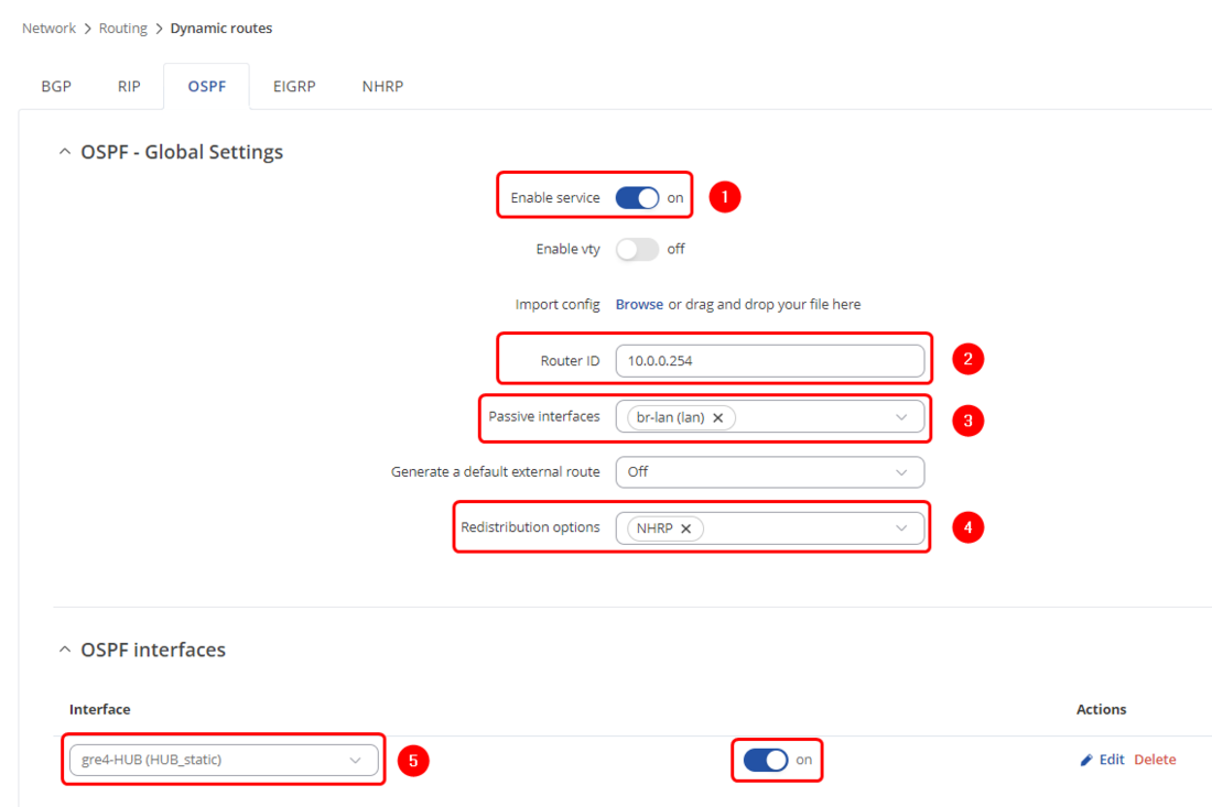
- 1. Enable Service - On
- 2. Router ID - 10.0.0.254
- 3. Passive interfaces - br-lan (all LAN interfaces)
- 4. Redistribution options - NHRP
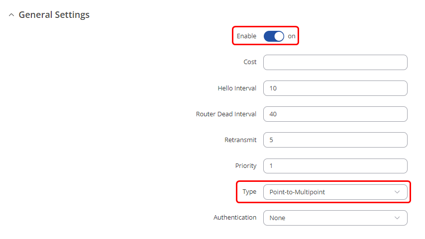
- 5. OSPF Interfaces - Create an entry, choose Type as Point-to-Multipoint and choose DMVPN interface as OSPF Interface and enable it
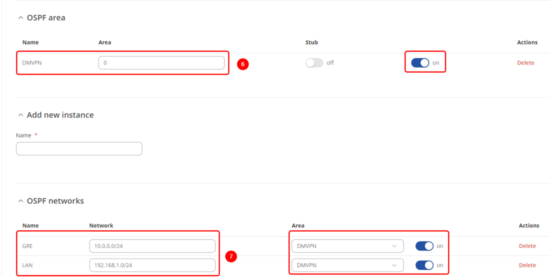
- 6. OSPF Area - Create an entry, input 0 to the Zone parameter and enable it
- 7. OSPF Networks - Create 2 entries, one network will be named GRE for VPN addresses 10.0.0.0/24, another networking will be named LAN for LAN addresses 192.168.254.0/24. Choose previously created OSPF Area entry and enable OSPF Networks
Spokes configuration
On the Spoke1 router, navigate to Network → Routing → Dynamic Routes → OSPF and configure OSPF as shown:
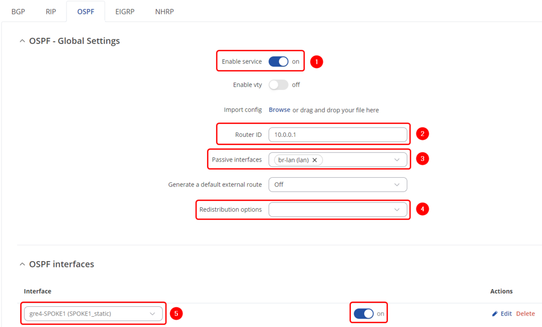


- 1. Enable Service - On
- 2. Router ID - 10.0.0.1
- 3. Passive interfaces - br-lan (all LAN interfaces)
- 4. Redistribution options - None
- 5. OSPF Interfaces - Create an entry, choose Type as Point-to-Multipoint and choose DMVPN interface as OSPF Interface and enable it
- 6. OSPF Area - Create an entry, input 0 to the Zone parameter and enable it
- 7. OSPF Networks - Create 2 entries, one network will be named GRE for VPN addresses 10.0.0.0/24, another networking will be named LAN for LAN addresses 192.168.1.0/24. Choose previously created OSPF Area entry and enable OSPF Networks
Configuration for the SPOKE2 will be analog to SPOKE1, with the exception of Router ID being 10.0.0.2 and OSPF Networks LAN entry's address being 192.168.2.0/24
Firewall Zones
This step should be done on DMVPN Hub and all spokes for OSPF to allow OSPF routes to their LAN networks.
Navigate to Network -> Firewall -> General settings -> Zones, set GRE zone to forward traffic to LAN and disable masquerading.

Testing the setup
If You have followed the steps correctly, configuration should be finished. These should be the results that You will be getting:
Routes on Spoke1:
root@RUTX11:~# ip route
default dev qmimux0 proto static scope link src WAN IP metric 1
10.0.0.2 nhid 30 via 10.0.0.254 dev gre4-SPOKE1 proto ospf metric 20 onlink
10.0.0.254 dev gre4-SPOKE1 proto static scope link
WAN IP dev qmimux0 proto static scope link metric 1
192.168.1.0/24 dev br-lan proto kernel scope link src 192.168.1.1
192.168.2.0/24 nhid 30 via 10.0.0.254 dev gre4-SPOKE1 proto ospf metric 20 onlink
192.168.254.0/24 nhid 30 via 10.0.0.254 dev gre4-SPOKE1 proto ospf metric 20 onlink
Routes on Spoke2:
root@RUTX11:~# ip route
default dev qmimux0 proto static scope link src WAN IP metric 1
10.0.0.1 nhid 41 via 10.0.0.254 dev gre4-SPOKE2 proto ospf metric 20 onlink
10.0.0.254 dev gre4-SPOKE2 proto static scope link
WAN IP dev qmimux0 proto static scope link metric 1
192.168.1.0/24 nhid 41 via 10.0.0.254 dev gre4-SPOKE2 proto ospf metric 20 onlink
192.168.2.0/24 dev br-lan proto kernel scope link src 192.168.2.1
192.168.254.0/24 nhid 41 via 10.0.0.254 dev gre4-SPOKE2 proto ospf metric 20 onlink
OSPF neighbors on HUB (done on FRR VTYSH package):

Spoke1 pinging Spoke2, traffic not going through HUB:
Spoke1:
root@RUTX11:~# ping 192.168.2.1
PING 192.168.2.1 (192.168.2.1): 56 data bytes
64 bytes from 192.168.2.1: seq=0 ttl=63 time=122.731 ms
64 bytes from 192.168.2.1: seq=1 ttl=63 time=123.373 ms
64 bytes from 192.168.2.1: seq=2 ttl=64 time=100.596 ms
64 bytes from 192.168.2.1: seq=3 ttl=64 time=100.323 ms
64 bytes from 192.168.2.1: seq=4 ttl=64 time=100.048 ms
HUB's traffic:
root@RUTXR1:~# tcpdump -i gre4-HUB
tcpdump: verbose output suppressed, use -v[v]... for full protocol decode
listening on gre4-HUB, link-type LINUX_SLL (Linux cooked v1), snapshot length 262144 bytes
11:56:27.429401 IP 10.0.0.254 > ospf-all.mcast.net: OSPFv2, Hello, length 52
11:56:27.429578 IP 10.0.0.254 > ospf-all.mcast.net: OSPFv2, Hello, length 52
11:56:28.334054 IP 10.0.0.254 > 10.0.0.2: OSPFv2, LS-Update, length 100
11:56:29.094679 IP 10.0.0.2 > ospf-all.mcast.net: OSPFv2, Hello, length 52
11:56:29.095649 IP 10.0.0.2 > ospf-all.mcast.net: OSPFv2, LS-Ack, length 44
11:56:35.381588 IP 10.0.0.1 > ospf-all.mcast.net: OSPFv2, Hello, length 52
