IPsec site to site configuration between Teltonika and Fortigate devices
The information in this page is updated in accordance with 00.07.07.2 firmware version.
The information in this page is updated in accordance with Fortigate v7.4.3 firmware version.
Introduction
Normally we configure IPsec for LAN-to-LAN communication, also known as split-tunnel VPN, when only specific hosts or subnets should be reachable via a VPN tunnel. However, we may also take a different approach and configure a VPN tunnel using the full tunnel method. This means that any non-directly connected network (i.e. lan interface) will be reachable only via IPsec tunnel and not via the typical default route.
Configuration overview and prerequisites
Before we begin, let's look at the configuration we are attempting to achieve and the prerequisites that make it possible.
Prerequisites:
- One RUT/RUTX series router or TRB gateway with RUTOS firmware;
- One Fortigate series router;
- An end device (PC, Laptop) for configuration;
If you're having trouble finding this page or some of the parameters described here on your device's WebUI, you should turn on "Advanced WebUI" mode. You can do that by clicking the "Advanced" button, located at the top of the WebUI.

Site to site configuration RUT public IP
This section provides a guide on how to configure a successful site to site IPsec vpn connection between RUT and Fortigate devices.
Topology
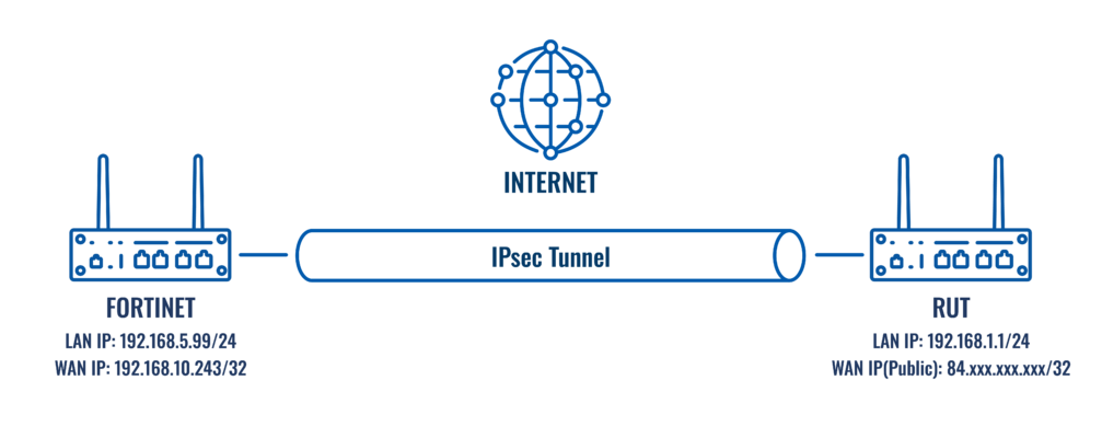
RUT – RUT will act as a hub. A hub is a server (IPsec responder), to which our spoke will be connected. It will be our remote endpoint for the spoke device. RUT has a LAN subnet of 192.168.1.0/24 and a WAN with Public IP, which should be reachable by the spoke.
Fortigate – Fortigate will act as a spoke. A spoke is a client (IPsec initiator), that will be connected to the hub. It will be connected to a hub to be able to reach RUT LAN subnet. Fortigate has a LAN subnet of 192.168.5.0/24 and a WAN with private IP.
Fortigate configuration
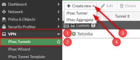
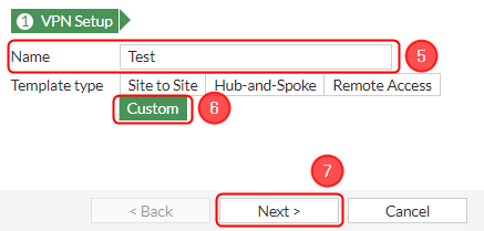
Start by configuring the Fortigate device. Login to the WebUI, navigate to 1. VPN → 2. IPsec Tunnels → 3. Create new → 4. IPsec Tunnel → 5. Your desired name → 6. Template type: Custom → 7. Click on the button next.
 |
|---|
 |
Note: Not specified fields can be left as is or changed according to your needs.
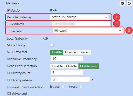
Network configuration
Configure everything as follows.
Make the following changes:
- Remote Gateway – Static IP Address;
- IP Address – RUT public IP;
- Interface – wan1;
Authentication configuration
Make the following changes:
- Method – Pre-shared Key;
- Pre-shared Key – your desired password;
- Version – 2;

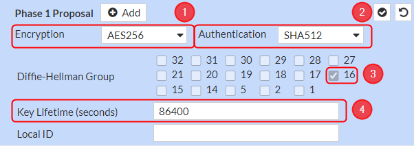
Phase 1 Proposal configuration
Note: This is only an example of a secure configuration. Other algorithms or even combinations of them could be used. However, we strongly recommend refraining from using older encryption and hashing algorithms unless support for certain legacy systems is required.
Make the following changes:
- Encryption – AES256;
- Authentication - SHA512;
- Diffie-Hellman Group – 16;
- Key Lifetime (seconds) – 86400;
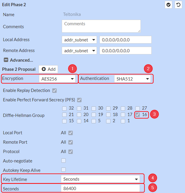
Phase 2 Selectors configuration
Note: This is only an example of a secure configuration. Other algorithms or even combinations of them could be used. However, we strongly recommend refraining from using older encryption and hashing algorithms unless support for certain legacy systems is required.
Make the following changes:
Click on Advanced settings;
- Encryption – AES256;
- Authentication - SHA512;
- Diffie-Hellman Group – 16;
- Key Lifetime – Seconds;
- Seconds – 86400;
Firewall configuration
After setting up our IPsec instance, we will need to configure our firewall accordingly. Navigate to Policy & Objects → Firewall Policy → and click on a Create new button.. Configure everything as follows.
In this example, we are allowing all types of traffic through the tunnel, but you can restrict certain traffic by specifying the services that are allowed via the tunnel.
Make the following changes:
- Incoming interface - lan;
- Outgoing interface - IPsec tunnel interface name (In this case it is Teltonika);
- Source - 192.168.5.0/255.255.255.0;
- Destination - 192.168.1.0/255.255.255.0;
- Service - ALL;
- NAT disabled;
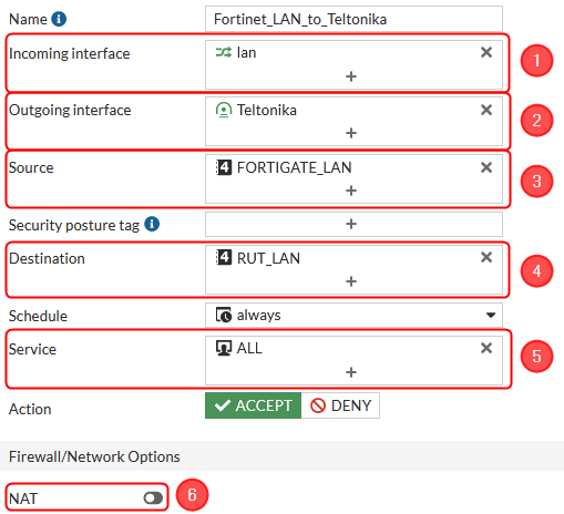
Then create a second firewall rule.
Make the following changes:
- Incoming interface - IPsec tunnel interface name (In this case it is Teltonika);
- Outgoing interface - lan;
- Source - 192.168.1.0/255.255.255.0;
- Destination - 192.168.5.0/255.255.255.0;
- Service - ALL;
- NAT disabled;
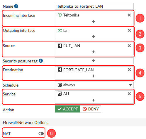
Our firewall should look like this:

Static Routes configuration
After setting up our IPsec instance and firewall, we will need to configure our static route accordingly. Navigate to Network → Static routes → and click on a Create new button.. For that we will need to create two static routes, one for blackhole and one for accessing our RUT device, configure everything as follows.
Make the following changes:
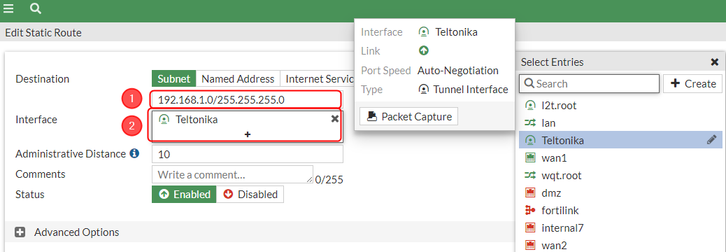 |
|
|---|---|
|
Then create a new static route for blackhole.
Make the following changes:
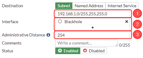 |
|
|---|---|
|
RUT configuration
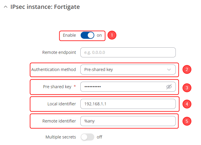
Start by configuring the RUT device. Login to the WebUI, navigate to Services → VPN → IPsec and add a new IPsec instance. Configure everything as follows. Note: Not specified fields can be left as is or changed according to your needs.
Instance configuration
Make the following changes:
- Enable instance;
- Authentication method - Pre-shared key;
- Pre-shared key - the same password you have set on Fortigate when configuring the Fortigate IPsec instance;
- Local identifier – RUT LAN IP;
- Remote identifier – %any;
Connection general section configuration
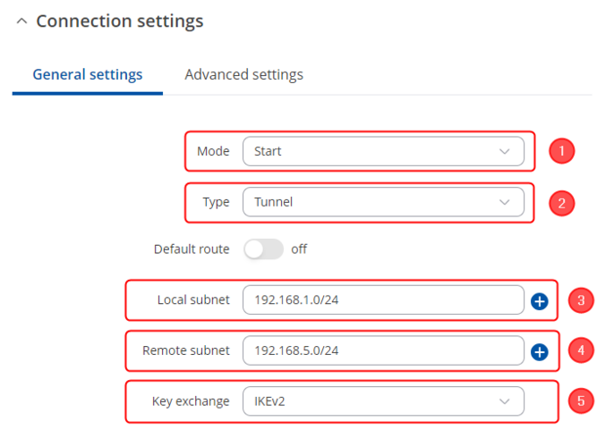
Make the following changes:
- Mode - Start;
- Type - Tunnel;
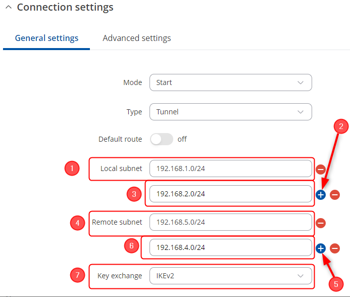
- Local subnet – 192.168.1.0/24;
- Remote subnet – 192.168.5.0/24;
- Key exchange - IKEv2;
Proposal configuration
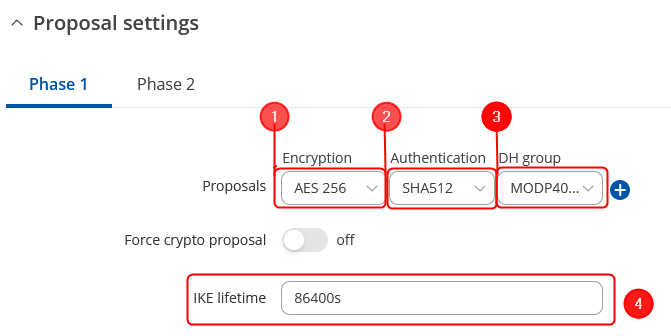
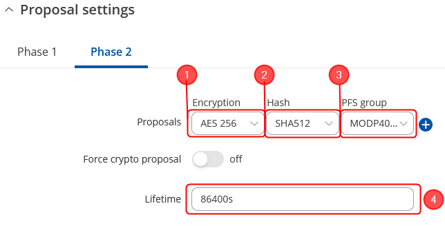
Note: This is only an example of a secure configuration. Other algorithms or even combinations of them could be used. However, we strongly recommend refraining from using older encryption and hashing algorithms unless support for certain legacy systems is required.
Make the following changes:
 |
|
|---|---|
|
 |
|
|---|---|
|
Site to site configuration with multiple LANs
This section provides a guide on how to configure a successful site to site IPsec vpn connection between RUT and Fortigate devices with multiple LANs.
Topology
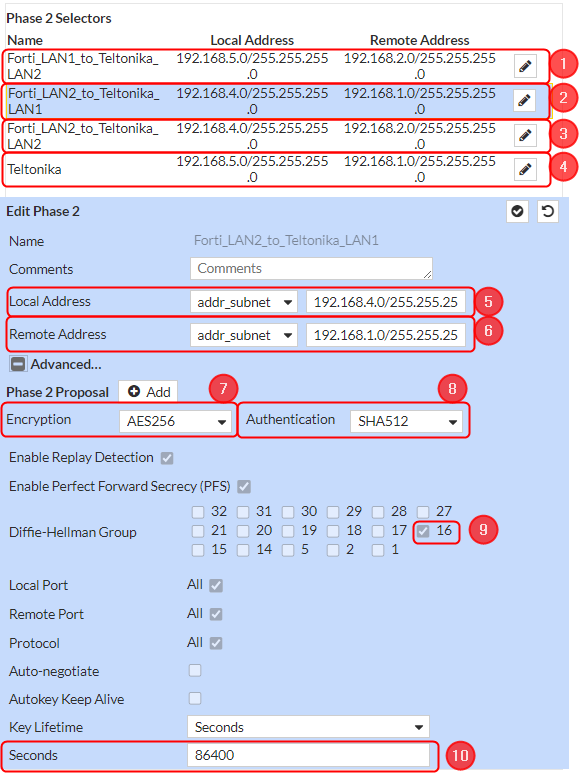
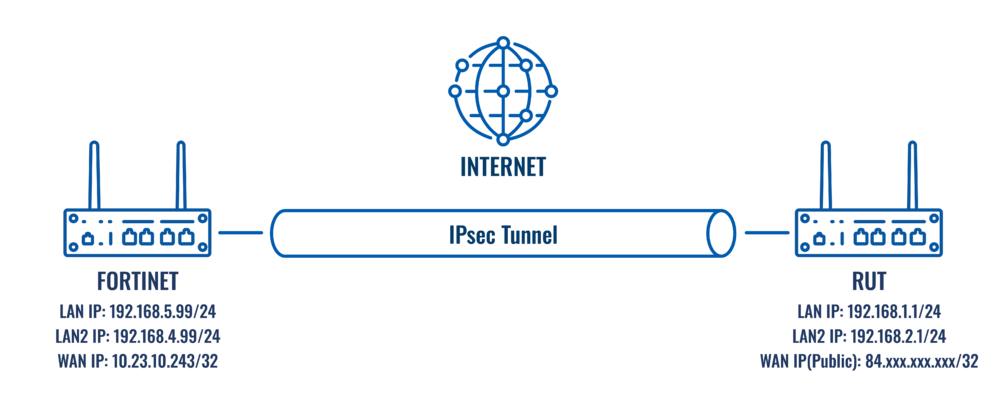
RUT – RUT will act as a hub. A hub is a server (IPsec responder), to which our spoke will be connected. It will be our remote endpoint for the spoke device. RUT has a LAN1 subnet of 192.168.1.0/24, LAN2 subnet of 192.168.2.0/24 and a WAN with Public IP, which should be reachable by the spoke.
Fortigate – Fortigate will act as a spoke. A spoke is a client (IPsec initiator), that will be connected to the hub. It will be connected to a hub to be able to reach RUT LAN1 and LAN2 subnet. Fortigate has a LAN1 subnet of 192.168.5.0/24, LAN2 subnet of 192.168.4.0/24 a WAN with private IP.
Fortigate configuration
As for the configuration of IPsec tunnel, everything is the same, only the Phase 2 Selectors, Firewall and static route sections will be configured additionally, so for other sections refer to the guide site to site.
Phase 2 Selectors configuration
Static route configuration
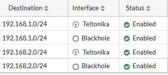
After setting up our IPsec instance and firewall, we will need to configure our static route accordingly. Navigate to Network → Static routes → and click on a Create new button. For that we will need to create four static route interfaces, two for blackholes and two for accessing our RUT device LAN1/LAN2, configure everything the same as for site to site, just add the LAN2. It should look like this:
RUT configuration
Then configure the RUT device. Login to the WebUI, navigate to Services → VPN → IPsec and add a new IPsec instance. Configure everything the same like site to site configuration, only change the Connection general section accordingly.
Connection general section configuration
Site to site configuration Fortigate public IP
This section provides a guide on how to configure a successful site to site IPsec vpn connection between RUT and Fortigate when Fortigate has a public IP and RUT is behind NAT. This setup will be similiar to Site to site configuration RUT public IP, we will need only to change network section on Fortigate and on RUT we will need to add Remote endpoint.
Topology
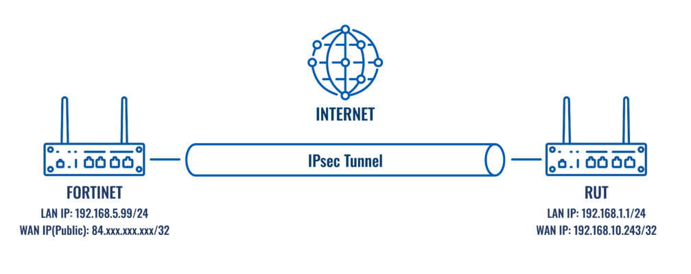
Fortigate – Fortigate will act as a hub. A hub is a server (IPsec responder), to which our spoke will be connected. It will be our remote endpoint for the spoke device. Fortigate has a LAN subnet of 192.168.5.0/24 and a WAN with Public IP, which should be reachable by the spoke.
RUT – RUT will act as a spoke. A spoke is a client (IPsec initiator), that will be connected to the hub. It will be connected to a hub to be able to reach Fortigate LAN subnet. RUT has a LAN subnet of 192.168.1.0/24 and a WAN with private IP.
Fortigate configuration
As for the configuration of IPsec tunnel, everything is the same, only the Network and authentication sections needs to be changed, so for other sections refer to the guide site to site. Start by configuring the Fortigate device. Login to the WebUI, navigate to 1. VPN → 2. IPsec Tunnels → 3. Create new → 4. IPsec Tunnel → 5. Your desired name → 6. Template type: Custom → 7. Click on the button next.
 |
|---|
 |
Note: Not specified fields can be left as is or changed according to your needs.
Network configuration
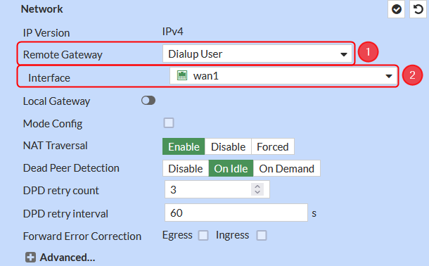
Make the following changes:
- Remote Gateway – Dialup User;
- Interface – wan1;
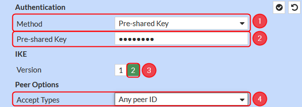
Authentication configuration
Make the following changes:
- Method – Pre-shared Key;
- Pre-shared Key – your desired password;
- Version – 2;
- Accept Types - Any peer ID;
RUT configuration
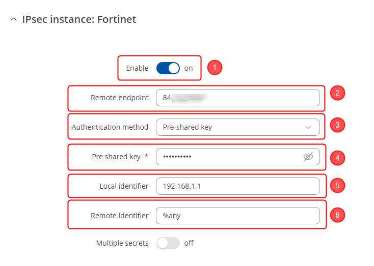
Start by configuring the RUT device. Login to the WebUI, navigate to Services → VPN → IPsec and add a new IPsec instance. Configure everything as follows. For other sections refer to the "Site to site configuration RUT public IP" Note: Not specified fields can be left as is or changed according to your needs.
Instance configuration
Make the following changes:
- Enable instance;
- Remote endpoint - Public IP of Fortigate device
- Authentication method - Pre-shared key;
- Pre-shared key - the same password you have set on Fortigate when configuring the Fortigate IPsec instance;
- Local identifier – RUT LAN IP;
- Remote identifier – %any;
Testing the configuration
If you have followed all the above steps, your configuration should be finished. But as with any other configuration, it is always wise to test the setup in order to make sure that it works properly.
Using the ipsec status or we can use ipsec statusall command for a more verbose output. With these commands we can see that the IPsec tunnel is successfully established on RUT router. The command output on a RUT device:

Also, we should be able to ping Fortigate device, we can check it out by executing this command via command line on RUT device: ping 192.168.5.99:

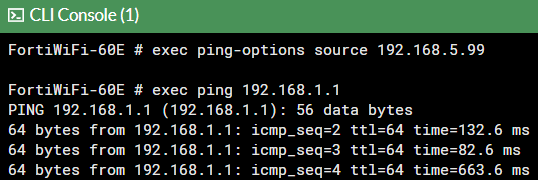
To check if IPsec tunnel is working properly from Fortigate, we can try pinging our RUT device by using this command in command line interface on Fortigateexec ping 192.168.1.1, if you are not able to ping RUT device, try changing the source interface from which we try pinging, by executing this command exec ping-options source 192.168.5.99:
We can also check if IPsec tunnel is working properly from Fortigate WebUI, navigate to VPN → IPSec Tunnels and there you will see if the tunnel is working:

See also
IPsec on Teltonika Networks devices

