RUT955 VPN: Difference between revisions
No edit summary |
No edit summary |
||
| Line 4: | Line 4: | ||
| series = RUT9xx | | series = RUT9xx | ||
<!--------------------------------OPENVPN-------------------------------> | <!--------------------------------OPENVPN-------------------------------> | ||
| file_openvpn_client_config = | | file_openvpn_client_config = Networking_rutxxx_vpn_openvpn_client_configuration_v2.png | ||
| file_openvpn_server_config = | | file_openvpn_server_config = Networking_rutxxx_vpn_openvpn_server_configuration_v2.png | ||
| file_openvpn_tls_clients_config = | | file_openvpn_tls_clients_config = Networking_rutxxx_vpn_openvpn_tls_clients_configuration_v2.png | ||
<!---------------------------------IPsec--------------------------------> | <!---------------------------------IPsec--------------------------------> | ||
| file_ipsec_config = | | file_ipsec_config = Networking_rutxxx_vpn_ipsec_ipsec_configuration_v2.png | ||
| file_ipsec_phase = | | file_ipsec_phase = Networking_rutxxx_vpn_ipsec_ipsec_configuration_phase_v2.png | ||
| file_ipsec_psk = Networking_rutxxx_vpn_ipsec_pre- | | file_ipsec_psk = Networking_rutxxx_vpn_ipsec_pre-shared_keys_v2.png | ||
| file_ipsec_main_mode = Networking_device_vpn_ipsec_main_mode_scheme_v3.png | | file_ipsec_main_mode = Networking_device_vpn_ipsec_main_mode_scheme_v3.png | ||
| file_ipsec_aggressive_mode = Networking_device_vpn_ipsec_aggressive_mode_scheme_v4.png | | file_ipsec_aggressive_mode = Networking_device_vpn_ipsec_aggressive_mode_scheme_v4.png | ||
Revision as of 09:42, 3 July 2019
Main Page > EOL Products > RUT955 > RUT955 Manual > RUT955 WebUI > RUT955 Services section > RUT955 VPNTemplate:Networking rutxxx manual vpn
GRE Tunnel
GRE (Generic Routing Encapsulation RFC2784) is a solution for tunneling RFC1812 private address-space traffic over an intermediate TCP/IP network such as the Internet. GRE tunneling does not use encryption it simply encapsulates data and sends it over the wide area network (WAN).
In the example network diagram two distant networks LAN1 and LAN2 are connected. To create A GRE tunnel the user must know the following parameters:
- Source and destination IP addresses
- Tunnel’s local IP address
- Distant network’s IP address and Subnet mask
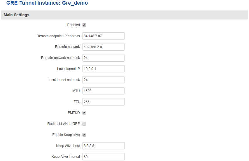
To create a new GRE instance, go to the GRE Tunnel tab, type in a name for your new instance in the text field below the GRE Tunnel tab and press the Add New button next to it. The newly created instance will be disabled and unconfigured. To configure it press the Edit button located next to it. This action will redirect you to the instance’s GRE Tunnel Configuration window.
| field name | value | description |
|---|---|---|
| Enabled | yes | no; Default: no | Toggles GRE Tunnel ON or OFF |
| Remote endpoint IP address | ip; Default: " " | WAN IP address or hostname of the remote GRE Tunnel instance |
| Remote network | integer [0..32]; Default: " " | LAN IP address of the remote device |
| Remote network netmask | integer [0..32]; Default: " " | LAN netmask of the remote device |
| Local tunnel IP | ip; Default: " " | Local virtual IP address. Can’t be in the same subnet as LAN network |
| MTU | integer [0..255]; Default: 255 | Toggles the Path Maximum Transmission Unit Discovery (PMTUD) status on this tunnel ON or OFF |
| TTL | integer [0..255]; Default: 255 | Fixed time-to-live (TTL) value on tunneled packets. The 0 is a special value meaning that packets inherit the TTL value |
| PMTUD | yes | no; Default: no | Toggles the Path Maximum Transmission Unit Discovery (PMTUD) status on this tunnel ON or OFF |
| Redirect LAN to GRE | yes | no; Default: no | Redirects LAN traffic to the GRE interface |
| Enable Keep alive | yes | no; Default: no | Gives the ability for one side to originate and receive keep alive packets to and from a remote router |
| Keep Alive host | host | ip; Default: " " | Keep Alive IP address to send pings to. Preferably this should be an IP address which belongs to the LAN network on the remote device |
| Keep alive interval | integer [0..255]; Default: " " | Frequency at which ICMP packets are sent by the Keep Alive function (in seconds) |
To find a more in-depth GRE Tunnel configuration example, visit this page
PPTP
Point-to-Point Tunneling Protocol (PPTP) is a protocol (set of communication rules) that allows corporations to extend their own corporate network through private "tunnels" over the public Internet. Effectively, a corporation uses a wide-area network as a single large local area network. A company no longer needs to lease its own lines for wide-area communication but can securely use the public networks.
For a more in-depth configuration example, visit the PPTP configuration examples page.
PPTP Client
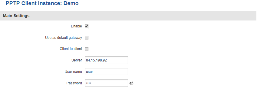
To create a new PPTP instance, go to the PPTP tab, select the Role (server or client) of your instance, type in a name in the New configuration name field and press the Add button next to it. The newly created instance will be disabled and unconfigured. To configure it click the Edit button located next to it. This action will redirect you to the instance’s PPTP Configuration window.
| field name | value | description |
|---|---|---|
| Enable | yes | no; Default: no | Toggles PPTP Client ON or OFF |
| Use as default gateway | yes | no; Default: no | Use this PPTP instance as default gateway |
| Client to client | yes | no; Default: no | Toggles client to client on the PPTP tunnel ON or OFF |
| Server | host | ip; Default: " " | PPTP server's IP address or hostname |
| Username | string; Default: " " | User name for authorization with the server |
| Password | string; Default: " " | Password used for authorization with the server |
PPTP Server
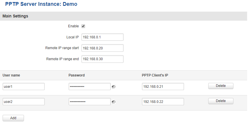
| field name | value | description |
|---|---|---|
| Enable | yes | no; Default: no | Toggles PPTP Server ON or OFF |
| Local IP | ip; Default: 192.168.0.1 | Virtual IP Address of this PPTP server |
| Remote IP range begin | ip; Default: 192.168.0.20 | Client IP address leases beginning |
| Remote IP range end | ip; Default: 192.168.0.30 | Client IP address leases end |
| User name | string; Default: youruser | Client's user name used for authentication with this server |
| Password | string; Default: yourpass | Client's password used for authentication with this server |
| PPTP Client's IP | ip; Default: " " | Client’s IP address. Leave empty to assign a random IP from the IP range specified above |
L2TP
In computer networking, Layer 2 Tunneling Protocol (L2TP) is a tunneling protocol used to support virtual private networks (VPNs). It is more secure than PPTP but, because it encapsulates the transferred date twice, but it is slower and uses more CPU power.
For a more in-depth configuration example, visit the L2TP configuration examples page.
L2TP Client
To create a new L2TP instance, go to the L2TP tab, select the Role (server or client) of your instance, type in a name in the New configuration name field and press the Add button next to it. The newly created instance will be disabled and unconfigured. To configure it press the Edit button located next to it. This action will redirect you to the instance’s L2TP Configuration window.
| field name | value | description |
|---|---|---|
| Enable | yes | no; Default: no | Toggles L2TP Client ON or OFF |
| Server | host | ip; Default: " " | L2TP server's remote IP address or hostname |
| Username | string; Default: " " | User name used to authenticate you to the L2TP server |
| Password | string; Default: " " | Password used to authenticate you to the server |
L2TP Server
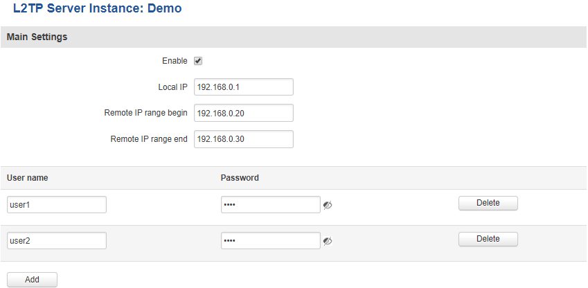
| field name | value | description |
|---|---|---|
| Enable | yes | no; Default: no | Toggles L2TP Server ON or OFF |
| Local IP | ip; Default: 192.168.0.1 | Virtual IP Address of this L2TP server |
| Remote IP range begin | ip; Default: 192.168.0.20 | Client IP address leases beginning |
| Remote IP range end | ip; Default: 192.168.0.30 | Client IP address leases end |
| User name | string; Default: user | Client's user name used for authentication with this server |
| Password | string; Default: pass | Client's password used for authentication with this server |
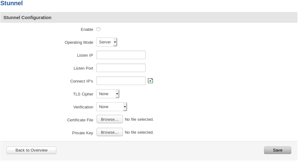
Stunnel Configuration
Default Stunnel configuration:
Stunnel configuration field explanation table:
| Field Name | Value | Description |
|---|---|---|
| Enabled | yes | no; Default: no | Enables the Stunnel configuration. |
| Operating Mode | Client | Server; Default: "" | Specifies whether this configuration will be used for Stunnel client or server. |
| Listen IP | ip | host; Default: "" | OPTIONAL Specifies which IP address or host should Stunnel listen to. If left empty, defaults to localhost. |
| Listen Port | port (integer [0..65535]); Default: "" | Specifies TCP port which Stunnel should listen to. Port cannot be taken by another service! |
| Connect IP's | [host:]port; Default: "" | Uses the standard host:port convetion (e.g. 127.0.0.1:6001; localhost:6001). Host part can be emmited - empty host part defaults to localhost. Must contain at least one item. If multiple options are specified, remote address is chosen using a round-robin algorithm. |
| TLS Cipher | None | Secure | Custom | Select permitted TLS ciphers (TLSv1.2 and below). If custom is selected, a new field appears to enter custom ciphers. |
| Allowed TLS Ciphers | Cipher[:Cipher]..; Default: "" | Only appears if a Custom TLS Cipher is selected A colon-delimited TLS cipher list (e.g. DES-CBC3-SHA:IDEA-CBC-MD5) |
| Application Protocol | Not specified | Connect | SMTP; Default: Not specified | CLIENT SIDE ONLY
This option enables initial, protocol-specific negotiation of the TLS encryption. The protocol option should not be used with TLS encryption on a separate port. If Connect or SMTP is selected, more customization fields appear. |
| Protocol Authentication | Connect: Basic | NTLM; Default: Basic SMTP: Plain | Login; Default: Plain | CLIENT SIDE ONLY
Options depend on the selected protocol Authentication type for the protocol negotiations. |
| Protocol Domain | domain (text); Default: "" | CLIENT SIDE ONLY
Only appears if a Connect protocol is selected Domain for the protocol negotiations. |
| Protocol Host | host:port; Default: "" | CLIENT SIDE ONLY
Only appears if a Connect protocol is selected Destination address for the protocol negotiations. Specifies the final TLS server to be connected to by the proxy, and not the proxy server directly connected by Stunnel. The proxy server should be specified with the connect option. |
| Protocol Username | username (text); Default: "" | CLIENT SIDE ONLY
Only appears if a protocol is selected Username for the protocol negotiations. |
| Protocol Password | password (text); Default: "" | CLIENT SIDE ONLY
Only appears if a protocol is selected Password for the protocol negotiations. |
| Verification | None | Verify Chain | Verify Peer; Default: None | Verification type. Verify Chain verifies connections against a Certificate Authority (CA) file, while Verify Peer verifies connections against a list of approved certificates. |
| Verification file | file; Default: "" | Only appears if a verification type is selected
File which is used to verify peer(s) or a peer chain. A different type of file is expected depending on the verification type selected: Verify Chain: Expects a CA (Certificate Authority) file. Verify Peer: Expects a file with one (or more, concatenated) peer certificate(s). |
| Certificate File | file; Default: "" | Mandatory for a server configuration. Optional for a client configuration
The parameter specifies the file containing certificates used by stunnel to authenticate itself against the remote client or server. The file should contain the whole certificate chain starting from the actual server/client certificate, and ending with the self-signed root CA certificate. Can be a certificate only, or both certificate and private key concatenated into a single file. |
| Private Key | file; Default: Certificate File | Can be skipped if the Certificate File is appended with the private key
Must be uploaded if the Certificate File does not contain the private key A private key, required to authenticate the certificate owner. |
After setting the parameters, click the Save button; otherwise, changes will not be saved. Some parameters will be shown in the configuration list table.
Stunnel Global Configuration
Default Stunnel global configuration:
Stunnel global configuration field explanation table:
| Field Name | Value | Description |
|---|---|---|
| Enabled | yes | no; Default: no | Enables/activates all the enabled Stunnel configurations. |
| Debug Level | integer [0..7]; Default: 5 | Debugging level. Level is one of the syslog level names or numbers emerg (0), alert (1), crit (2), err (3), warning (4), notice (5), info (6), or debug (7). All logs for the specified level and all levels numerically less than it will be shown. Use 7 for greatest debugging output. |
| Use alternative config | yes | no; Default: no | Enable alternative configuration option (Config upload). Be aware that when using alternative configuration, all configurations in Stunnel Configuration section will be skipped. |
| Upload alternative config | file; Default: "" | Only appears if the "Use alternative config" is enabled Upload the alternative Stunnel configuration file. |
IMPORTANT:
The router can have multiple configurations set up and enabled at the same time. Note that if at least one configuration is not set correctly, none of them will be enabled, despite the "Enabled" flag being marked.
Also, you must mark the global "Enabled" flag to actually enable all the individually marked configurations.
DMVPN
Click here for DMVPN configuration instructions.
See also
- Configuration examples for RUTxxx VPN services:
- Configuration examples for third party VPN services
- Other related examples:


