Tailscale Configuration Example
The information on this page is updated in accordance with 00.07.06.3 firmware version.
Introduction
Tailscale is a straightforward peer-to-peer VPN service that utilizes the open-source WireGuard protocol. This page provides an example of how to configure Tailscale VPN nodes, including the option to use one of the nodes as an exit node.
Note: Tailscale is additional software that can be installed from the System → Package Manager page.
The Tailscale VPN package is compatible exclusively with TRB1 (excluding TRB160), TRB5, RUTX and RUTM series devices. This is because Tailscale demands a larger amount of flash space, which surpasses the capacity available on our other devices.
Prerequisites
- A RUTX series device (this example will use RUTX12)
- An end device to configure devices (PC, Laptop, Tablet, or Smartphone)
- Activated Tailscale account. You can register here.
End results
In the end, a secure tunnel will be established between RUTX12 and any of your devices. We can also utilize RUTX12 as the endpoint device, serving as the point through which our connection reaches the internet. This means that our device will have the IP address of RUTX12.
Tailscale instances
RUTX12 Tailscale configuration
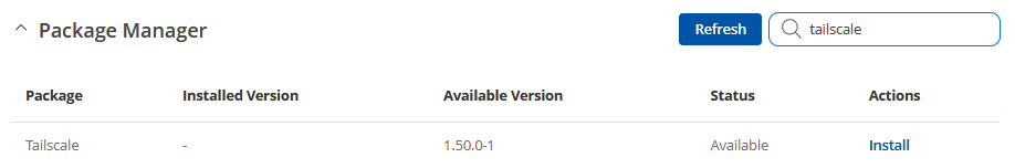
- First, let's start by installing the Tailscale package on our router. To accomplish this, navigate to System -> Package Manager -> Packages.
- Here, you can find it easily by typing "Tailscale" in the search bar as portrayed below.
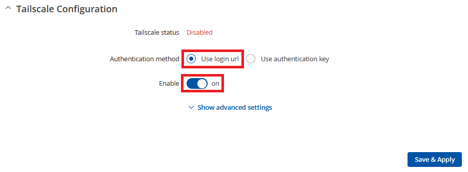
- Once the package is installed, you can go to "Services" -> "VPN" -> "Tailscale" to access the corresponding window.
- The setup process is straightforward. Simply choose "Use login URL" (for increased security and you can use the "Authentication Key," but login will still be required) and activate the service by enabling it and pressing the button "Save & Apply".
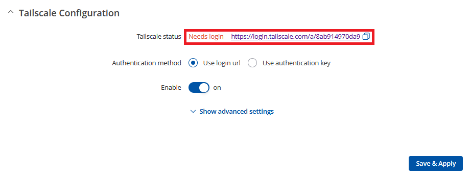
- Once enabled, you'll see a login link that will direct you to the Tailscale website. There, you can connect RUTX12 to the account you created before starting. If the link is not visible, try saving the configuration and reloading the page.
- Follow the instructions to connect your device. If everything is successful, you should see a similar success message.
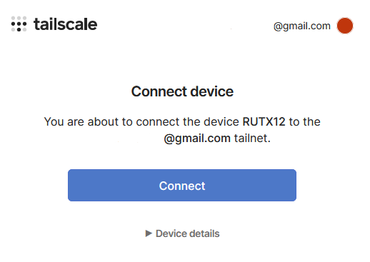
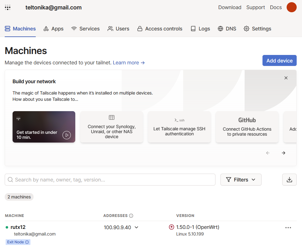
- Now, you will be redirected to your admin console and with that, the RUTX12 setup is complete.


Another end device configuration
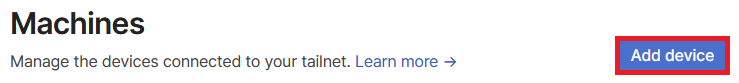
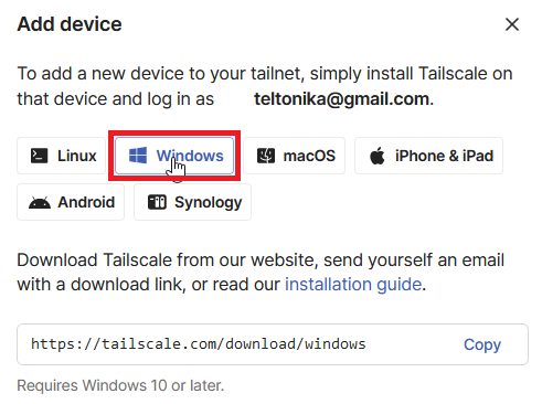
- Select another end device you intend to use, whether it's a PC, laptop, mobile phone, or any other device. Then, click the "Add device" button.
- Afterward, choose the specific device you will be using. For this setup, we'll be selecting a Windows laptop.
- Once the selected software is installed, go to the taskbar and click on the Tailscale icon.
- You will be redirected to another page where you need to connect this device. Proceed to connect it.
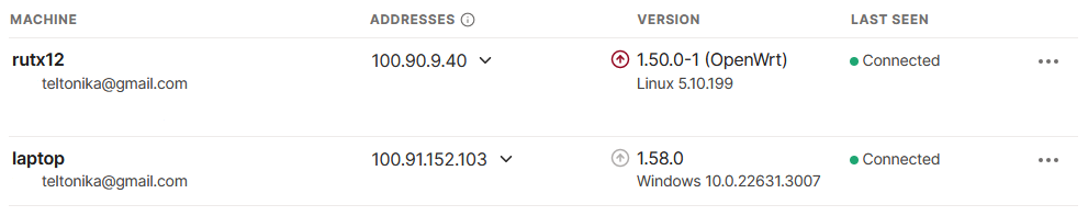
- Now, you will be redirected once again to the admin console, where both devices will be visible.


Testing configuration
To test connection you need to open Command Line Interface on RUTX12 (Services → CLI) and login. Then type:
tailscale status
Both instances should be connected, and the output should resemble the following.

Now, you can try pinging devices using VPN addresses and even machine names provided by Tailscale. Note that machine names can be changed. If everything is set up correctly, the ping should return results in a similar fashion as shown in the image below.


Configuring Tailscale exit node
To begin, in the Service -> VPN -> Tailscale press "Show advanced settings" and enable "Exit node" slider.

After completing this step, go to the control panel on your laptop. In Tailscale, choose "exit node" -> RUTX12. This should complete the process, and now the traffic from your laptop will pass through the exit node RUTX12, with your laptop's traffic having the IP address of RUTX12.
Configuring Advertised routes
Advertised routes refer to LAN networks behind the device advertising them. These networks are accessible to other Tailscale VPN clients.
Configuring it is quite simple. First, add the LAN network you want to access from other Tailscale VPN devices. In this case, we are selecting the network 192.168.1.0/24 and saving the configuration by pressing "Save & Apply."

Next, navigate to the Tailscale admin, where you'll notice that "Subnets" are already enabled from our router's side.

To complete the setup, we'll need to approve it from the console. Access the RUTX12 settings by clicking on the three-dot icon.

A pop-up window will appear. Here, enable your advertised subnet by checking the checkbox and then clicking the "Save" button.

Now, you'll be able to access that advertised LAN network from other Tailscale VPN clients.
See also
- Other types of VPNs suported by RUTX devices:
References
Tailscale - Main Tailscale website
CLI - Tutorial how to access CLI via WebUI